Copyright HK Instruments 2018 www.hkinstruments. Installaon version 6.0 2018
STEP 4: SELECTING THE MEASUREMENT UNIT
1)Selectthedesiredmeasurementunit.(seestep4)
2)Selectthedesiredmeasurementrange.(seestep5)
3)Selectthedesiredresponseme.(seestep6)
4)Zerothedevice.(seestep7)
5)Connectthepressuretubes.Connectposivepressureto
portlabeled“+”andnegavepressuretoport“-”.
6)Closethelid.Thedeviceisnowreadytobeused.
STEP 3: CONFIGURATION
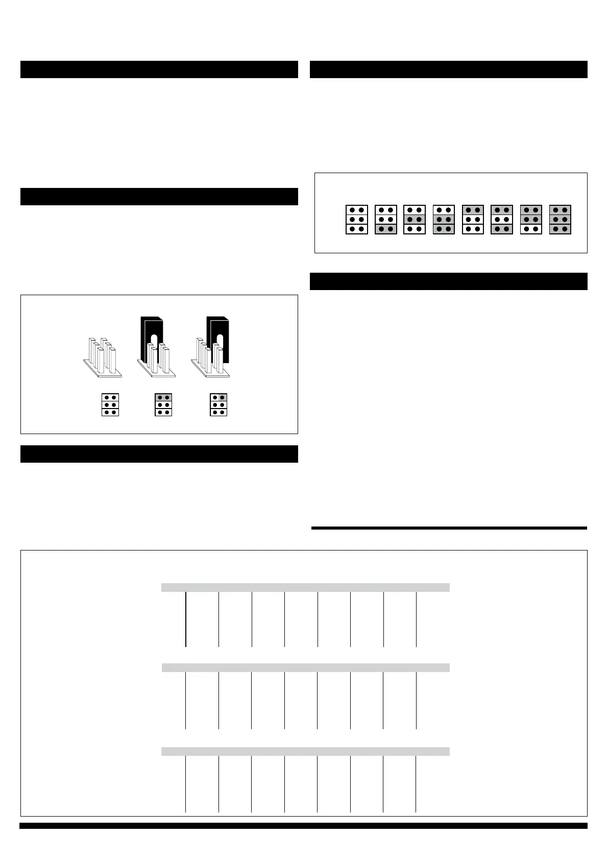
No jumper
Circuit open
Jumper storedJumper installed
Circuit closed
(Grey colour indicates that a jumper is installed)
Figure 3 - Jumper installaon
2)InstalljumpersonJ1,J2andJ3asrequired.
a.Usingtherangenumberfrom1cabove,ndthecorresponding
rangenumberinChart2.
b.InstalljumpersonJ1,J2andJ3ondevice,asshownundertherange
numberinChart2.(Greycolourindicatesthatajumperisinstalled.
Referencegure3forjumperinstallaon.)
1)Tochangethemeasurementunitappearingonthedisplay,installa
jumpertobothpinsofJ5(seeFigure3).
2)Pushdownthezerobuonandthemeasurementunitopons(Pa,
kPa,mbar,inchWC,mmWC,psi)willcycleonthedisplay.
3)Toselectaunitopontodisplay,removethejumperfromJ5
whilethemeasurementunitisvisibleonthedisplay.
Range 1 Range 2 Range 3 Range 4 Range 5 Range 6 Range 7 Range 8
Pa
kPa
mbar
inchWC
0–25
0–0.025
0–0.25
0–0.10
0–50
0–0.05
0–0.50
0–0.20
0–100
0–0.1
0–1.00
0–0.40
0–250
0–0.25
0–2.50
0–1.00
-25–25
-0.025–0.025
-0.25–0.25
-0.10–0.10
-50–50
-0.05–0.05
-0.50–0.50
-0.20–0.20
-100–100
-0.1–0.1
-1.0–1.00
-0.40–0.40
-150–150
-0.15–0.15
-1.50–1.50
-0.60–0.60
Model DPT250-R8
Model DPT2500-R8
Range 1 Range 2 Range 3 Range 4 Range 5 Range 6 Range 7 Range 8
Pa
kPa
mbar
inchWC
-100–100
-0.10–0.10
-1.00–1.00
-0.40–0.40
0–100
0–0.10
0–1.00
0–0.40
0–250
0–0.25
0–2.50
0–1.00
0–500
0–0.50
0–5.00
0–2.00
0–1000
0–1.00
0–10.0
0–4.00
0–1500
0–1.50
0–15.0
0–6.00
0–2000
0–2.00
0–20.0
0–8.00
0–2500
0–2.50
0–25.0
0–10.00
Model DPT7000-R8
Pa
kPa
mbar
inchWC
0–1000
0–1.00
0–10.0
0–4.00
0–1500
0–1.50
0–15.0
0–6.00
0–2000
0–2.0
0–20.0
0–8.00
0–2500
0–2.50
0–25.0
0–10.0
0–3000
0–3.00
0–30.0
0–12.00
0–4000
0–4.00
0–40.0
0–16.00
0–5000
0–5.00
0–50.0
0–20.00
0–7000
0–7.00
0–70.0
0–28.00
Range 1 Range 2 Range 3 Range 4 Range 5 Range 6 Range 7 Range 8
mmWC
psi
mmWC
psi
mmWC
psi
0–2.6
0–0.0036
0–5.1
0–0.0073
0–10.2
0–0.0145
0–25.5
0–0.0363
-2.6–2.6
-0.0036–0.0036
-5.1–5.1
-0.0073–0.0073
-10.2–10.2
-0.0145–0.0145
-15.3–15.3
-0.0036–0.0036
-10.2–10.2
-0.0145–0.0145
0–10.2
0–0.0145
0–25.5
0–0.0363
0–51.0
0–0.0725
0–102.0
0–0.1450
0–153.0
0–0.21725
0–204.0
0–0.2900
0–255.0
0–0.3625
0–102.0
0–0.1450
0–153.0
0–0.21725
0–204.0
0–0.2900
0–255.0
0–0.3625
0–306.0
0–0.4350
0–408.0
0–0.5800
0–510.0
0–0.7250
0–714.0
0–1.0150
SELECTING THE MEASUREMENT RANGE CONTINUED
Chart 1
Range 7 Range 8Range 1 Range 2 Range 3 Range 4 Range 5 Range 6
Jumper J1
Jumper J2
Jumper J3
(Grey colour indicates that a jumper is installed. Reference Figure 3 and Schemacs for jumper installaon.)
Chart 2
Theresponsemeaectshowfastthetransmierreactstochangesin
thesystem.Theresponsemeisthemethedevicetakestoreach63
%ofthemeasuredvalue.Tosmoothoutunstablepressureuctuaons
inairowapplicaons,selectalongerresponseme.
Example:
Selectedresponseme:8.0seconds
Result: Output signal achieves a new value in 20 seconds (Response
me*5)
Tochangeresponseme,installorremovejumperonJ4.
(seeFigure3)
1)InstalljumperonJ4for8.0secondresponseme.
2)RemovejumperfromJ4for0.8secondresponseme.
STEP 6: SELECTING THE RESPONSE TIME
STEP 5: SELECTING THE MEASUREMENT RANGE
1)Determinetherangenumber
a.FindthemodelinChart1.
b.Findthemeasurmentunit(selectedinstep4).
c.Findtherequiredmeasurementrangeonthesamelineasthe
measurementunit(babove)anddeterminetherangenumberinthe
header.
 Loading...