
P
Peter GarzaJul 29, 2025
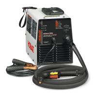
What to do if labels are damaged on Hobart Welding Products AirForce 12ci?
- SStephen RiveraJul 29, 2025
If you find that the labels on your Hobart Welding Products Welding System are damaged or unreadable, the suggested solution is to replace them.