Do you have a question about the Hobbywing X-Rotor F7 and is the answer not in the manual?
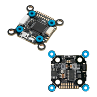
This document describes the HOBBYWING F7 Flight Controller, a device designed for FPV (First Person View) racing aircraft, offering a range of features for flight control, parameter adjustment, and connectivity.
The F7 Flight Controller serves as the central processing unit for an FPV drone, managing flight dynamics and various peripheral interactions. Its core function is to execute the PID (Proportional-Integral-Derivative) loop, which is critical for stable and responsive flight. The STM32 F722 MCU enables high-frequency operation for both the PID loop and the gyroscope, contributing to precise control.
An onboard OSD (On-Screen Display) microchip, utilizing DMA (Direct Memory Access) mode, allows users to view and adjust flight parameters directly on their video feed. This OSD functionality is controlled by an F4 MCU, ensuring efficient operation. The FC is compatible with Betaflight firmware, an open-source program that facilitates comprehensive parameter adjustment and flight configuration. This makes the controller particularly well-suited for the demanding environment of FPV racing, where fine-tuning is essential for optimal performance.
The integrated Flash chip provides the capability to record and save flight data, often referred to as "black box" data. This feature is invaluable for post-flight analysis, allowing users to review flight characteristics, identify issues, and refine their aircraft's setup.
The controller supports a wide array of receiver types, including SBUS, SUMH, SUMD, SPEKTRUM1024/2048, and XBUS. This broad compatibility ensures flexibility in choosing a radio control system.
For visual feedback and customization, the FC includes an LED strip signal output port. This allows users to control the color and flash mode of WS2812B LED strips, adding a personalized touch to their drone.
Monitoring the aircraft's power system is facilitated by a Volt/Amp monitoring port. This port enables users to check the battery voltage (via the BAT port) and current draw (via the CRT port, requiring an external current meter). This information is crucial for managing flight time and battery health.
An output port for a buzzer allows for the connection of external buzzers. These buzzers provide audible warnings and inform the pilot about various flight statuses, such as low battery or lost signal, enhancing safety and operational awareness.
The Micro USB port is a primary interface for connecting the FC to a PC. This connection is used for flashing firmware updates and adjusting all flight parameters through the Betaflight software.
The FC incorporates a board load with 5V and 10V BEC (Battery Eliminator Circuit) outputs, each capable of supplying 2A. These BECs provide power to various peripheral devices, including the receiver, VTX (Video Transmitter), LED lamps, and other accessories, simplifying the power distribution system.
A unique feature is the switch module for the board load graphic transmission (VTX). This module allows for remote control of the VTX's power switch, offering convenience during flight operations.
The FC also includes specific ports for advanced connectivity:
The F7 Flight Controller is designed for ease of use and extensive customization, particularly for FPV enthusiasts.
set spektrum_sat_bind= 9, set spektrum_sat_bind_autorst= 0, and save) are entered to initiate the binding. After a power cycle, the receiver's LED will flash rapidly, indicating binding mode. The transmitter is then turned on to complete the binding. If successful, the LED will turn solid. If not, the spektrum_sat_bind value can be adjusted and retried. Once bound, set spektrum_sat_bind = 0 and save are entered in the CLI to finalize the setup.The VTX switch module allows remote control of VTX power. This is configured via the Betaflight CLI and Modes tab. Users first identify the UART TX/RX pad resource ID (e.g., RX5 is D02). The resource is then cleared from its assigned function (resource SERIAL_RX 5 NONE) and reassigned to a custom mode switch (resource PINIO 1 D02). After saving and rebooting, an AUX channel is assigned to the USER1 mode in the Modes tab, allowing the VTX power (10V) to be turned on or off with a transmitter switch.
The FC supports switching between two cameras (Camera 1 and Camera 2). Camera 1 is the default signal. This feature is configured in the Betaflight Modes setting, where USER2 is used to select between Camera 1 and Camera 2.
To flash new firmware, the FC must be put into "DFU" (Device Firmware Upgrade) mode. This requires the Zadig software tool to switch the FC's driver to "DFU" mode.
The Betaflight software is essential for adjusting FC parameters. This software runs as an extended application in Google Chrome and can be downloaded from the Google App Store or GitHub. After connecting the FC to a computer, users can access relevant web pages to download the software. Once connected, parameters can be adjusted. Drivers for CP210x, STM USB VCP, and Zadig for Windows DFU flashing are also available for download.
The manual emphasizes several aspects related to the maintenance and care of the F7 Flight Controller.
Users are advised to ensure all wires and connections are well insulated before connecting the unit to other devices to prevent short circuits, which can cause damage. Proper soldering of all wires and connectors is critical, and users should avoid getting solder tin on electronic components. The manufacturer explicitly states that they will not be responsible for damage resulting from improper soldering or installation.
The manual warns against using joint pins other than those included in the product box for connecting the FC to the ESC and image-transferring board. The heights of the pins and sockets are regulated and fixed. Using pins that are too short can deform the PCBs, while pins that are too long can affect connections and damage relevant devices. The manufacturer will not be responsible for damage or losses due to user carelessness in this regard.
To ensure longevity and proper functioning, the unit should never be used near heat, moisture, strong acid, alkali, or any other environmental conditions that are detrimental to electronic components.
While the unit comes pre-flashed with firmware from the factory, the manufacturer will not be liable for any damage resulting from firmware flashing carried out by users. The FC firmware is open-source, and users are encouraged to seek technical information online. The manufacturer does not provide technical support beyond the FC hardware.
This user manual is based on the Betaflight operation manual and serves as a reference. Due to potential firmware updates or other reasons, the descriptions of functions may differ, and users are advised to always refer to the official Betaflight manual as the standard.
A critical warning is issued against flying the aircraft near crowds. The manufacturer explicitly states that they will not assume any losses resulting from aircraft crashes.
| MCU | STM32F745 |
|---|---|
| Input Voltage | 3-6S LiPo |
| Gyroscope/IMU | MPU6000 |
| Barometer | No |
| OSD | Yes |
| Black Box | Yes |
| Current Sensor | Yes |
| Dimensions | 36x36mm |
| Mounting Holes | 30.5x30.5mm |
| Weight | 10g |
| Processor | ARM Cortex-M7 |
| Firmware | Hobbywing |
| BEC | 5V/3A |
| ESC Signal | PWM |