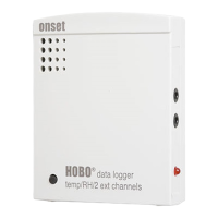
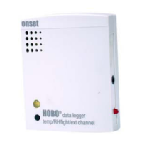
HOBO U12 4-External Channel Outdoor/Industrial Data Logger
© 2009 Onset Computer Corporation
Part #: MAN-U12008, Doc #: 13132-A
Accessories
• Replacement Parts Kit (Part # H8X4-BK)
• Replacement Desiccant (Part # DESIC-PACK)
• U-Bolt (Part # U-BOLT-KIT)
4-20mA Input cable
This cable (part number CABLE-4-20mA) measures current from 0 to 20.1 mA. Do not expose to current above 20 mA or
to negative current. Do not cut off the end of the gray cable where it connects to the blue and yellow wires, as it contains the
precision resistor required for current measurement. If you are using this cable outdoors, you will need to ensure that the
connection to your sensor or device is also weatherproof. The connection between the gray cable and yellow and blue wires
is splash-proof, but not weatherproof.
Voltage input cable
The logger’s external inputs can accept the voltage input cable (Onset part number CABLE-2.5-STEREO), which allows a
voltage to be recorded. The input line must not be exposed to signals below 0 V or above 2.5 V. If you are using this cable
outdoors, you will need to ensure that the connection to your sensor or device is also weatherproof.
Voltage Input Cable Connections
Wire Connection
Red Switched 2.5 V output
White Voltage input
Black Ground
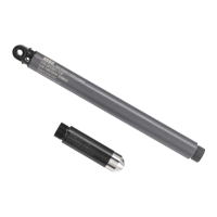
Other external sensors
Onset has a range of external temperature sensors, AC current sensors, and cables for incorporating other sensors that are
compatible with the U12 4-External Channel Data Logger. Measurement specifications for using Onset temperature and AC
current sensors with this logger are provided in the sensor manuals. For compatible sensors, refer to the HOBO catalog,
contact Onset Computer Corporation, or contact an Onset Authorized Dealer.
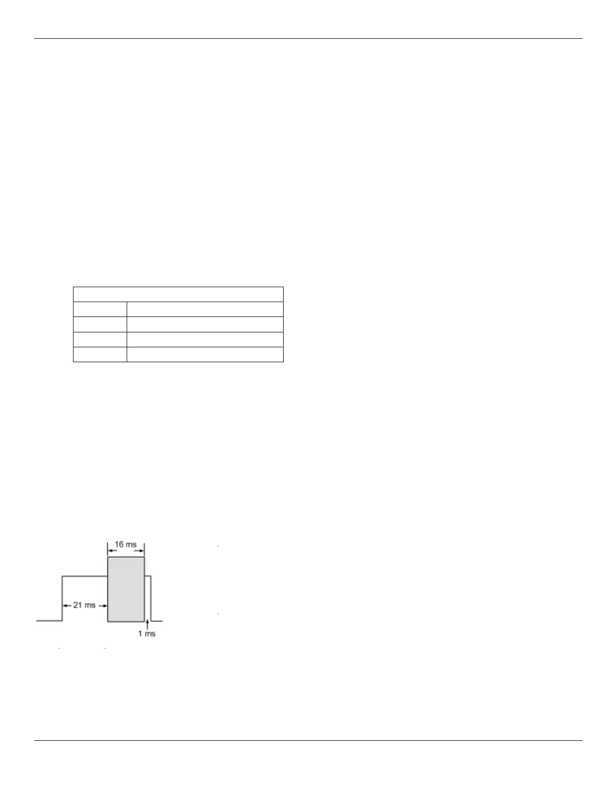
Switched 2.5 V output
The external input channels have a switched 2.5 V output. This signal can be used to power a sensor directly, or it can be
used to trigger an external circuit. External sensors should draw no more than 4 mA total when powered. The switched 2.5
V output turns on about 21 ms before the external channels are measured and stays powered for 1 ms after the external
channels are measured, as shown in the diagram. The grey area shows the 16 ms period during which the logger samples the
input signals.
When using multiple voltage and/or current inputs, the (-) from your current source(s) and the 0 V line of your voltage
source(s) are tied together at the logger. If these lines are at different voltage potentials, this may cause inaccurate readings
or even damage your logger. Keep in mind that these lines may also be tied to earth ground through your PC interface cable
when connected to your computer. Special precautions may be necessary if any of your voltage or current source common
lines are not tied to earth ground. Input isolators may be needed in industrial environments to prevent errors caused by
ground loops.
 Loading...