14
Adres producenta/ Adresse des Herstellers/ Manufacturer’s Address/ Адрес производителя
GTV Poland Sp. z o.o. Sp. k., ul. Przejazdowa 21, 05-800 Pruszków
5-9 Diode and continuity
Range Description Note
An approximate for-ward
drop in voltage will be
displayed
The voltage in an open
circuit is about 1.5 V.
Built-in buzzer sounds
when the resistance is less
than about 30 Ω
The voltage in an open
circuit is about 0.5 V.
Overload protection: 250 V DC/AC RMS
For the continuity test: when the resistance is 30 Ω to 70 Ω, the buzzer may or may not sound.
When the resistance is greater than 70 Ω, the buzzer will not sound.
5–10. Capacity
Range Resolution Accuracy
60 nF 10 pF
±(8% reading + 5 digits)
600 nF 100 pF
6 uF 1 nF
60 uF 10 nF
600 uF 100 nF
60 mF 100 uF
Overload protection: fuse F0.4A / 600 V.
Open circuit voltage: about 0.5 V.
5-11. FREQUENCY (automatic range selection)
Range Accuracy
0~60MHz ±(1.0% + 5)
Overload protection: 250 V DC/AC RMS
5–12. Battery
Range Resolution Discharge resistance
1.5 V 0.01 V 25 Ω
3 V 0.01 V 90 Ω
9 V 0.01 V 220 Ω
Overload protection 1.5 V and 3 V.
Ranges Fuse F0.4A / 250V 9 V.
Range 250 VDC / AC RMS
The battery voltage is shown on the LCD.
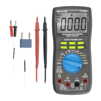
6. MEASUREMENTS
6-1. Voltage measurement
1) Connect the black lead to the COM socket and the red lead to the IMPUT socket
2) Set the function switch to V
lub V . Select automatic range or manual range with the „RANGE” button.
3) In the manual range, if the measured voltage is not known, select the highest range.
4) Connect test leads to the source or measured circuit.
5) Read the result on the screen. The polarity of the red lead connection will be indicated during the DC measurement.
Note:
a. |n a small range, the meter may display an unstable reading when the test leads are not connected to the circuit. This is normal
and will not affect the measurements.
b. In the manual range mode, when the meter shows an overrange, the symbol „OL” displays, select a higher range.
c. To avoid damage to the meter, do not measure a voltage over 600 V DC (for DC measurement) or 600 V AC (for AC measure-
ment). Complies with CATIII.