Do you have a question about the Hokkaido HCKU 565 X2R and is the answer not in the manual?
| Brand | Hokkaido |
|---|---|
| Model | HCKU 565 X2R |
| Category | Air Conditioner |
| Language | English |
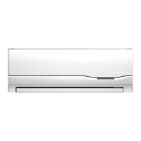
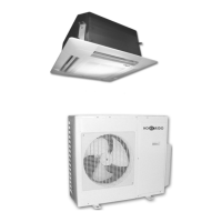
Details on various indoor unit models, dimensions, weights, and power supply.
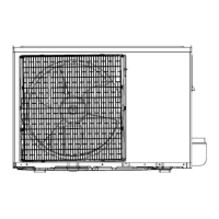
Details on various outdoor unit models, dimensions, weights, and power supply.
Lists cooling and heating capacities for HCKU 565 X2R with various indoor unit combinations.
Details cooling and heating capacities for HCKU 805 X3R with multiple indoor unit options.
Provides cooling and heating capacity data for HCKU 855 X4R with various indoor unit pairings.
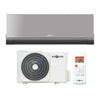
Detailed specifications for the wall-mounted series, including power, cooling, heating, and components.
Provides dimensions for HKEU 265 XR and HKEU 355 XR wall-mounted indoor units.
Schematic showing the indoor unit's electrical connections and components.
Schematic illustrating the refrigerant piping for the HCKU 565 X2R unit.
Diagram showing the refrigerant piping configuration for the HCKU 805 X3R unit.
Illustrates the refrigerant piping system for the HCKU 855 X4R outdoor unit.
Detailed wiring schematic for the HCKU 565 X2R outdoor unit.
Wiring diagram detailing the electrical connections for the HCKU 805 X3R outdoor unit.
Electrical wiring schematic for the HCKU 855 X4R outdoor unit.
Error codes (E0-E6, P0-P3, P5) and their meanings for Corona DC inverter indoor units.
Error codes (E0-E6, P0-P3) and their meanings for Alfa DC inverter indoor units.
Error codes (E0-E6, P0-P5) and their meanings for Vertu DC inverter indoor units.
Step-by-step guide for diagnosing and resolving EEPROM errors (E0) on indoor units.
Diagnostic steps for outdoor communication errors (E1) on indoor units.
Procedure for diagnosing zero-crossing examination errors (E2) on indoor units.
Guide to troubleshoot fan speed control issues (E3) on indoor units.
Diagnosing outdoor unit sensor issues (E5) affecting indoor units.
Troubleshooting steps for indoor/evaporator sensor faults (E6).
Diagnosing and resolving inverter module protection issues (P0).
Troubleshooting outdoor voltage protection (P1) for indoor units.
Diagnosing compressor top protection against temperature (P2).
Explanation of LED error codes E0 through E7 for outdoor unit malfunctions.
Explanation of LED protection codes P0 through P6 for outdoor unit protections.
Diagnostic procedure for 'No 1 Indoor unit pipe temp. sensor defective' error (E1).
Troubleshooting guide for 'No 2 Indoor unit pipe temp. sensor defective' error (E2).
Procedure for 'No 3 Indoor unit pipe temp. sensor defective' error (E3) diagnosis.
Diagnosing outdoor unit sensor defects (E4).
Troubleshooting compressor voltage protection (E5).
Diagnostic steps for 'No 4 Indoor unit pipe temp. sensor defective' error (E6).
Troubleshooting communication errors between outdoor IC and DSP (E7).
Diagnosing compressor discharge temperature protection (P0).
Diagnosing and resolving high pressure protection (P1).
Troubleshooting low pressure protection (P2) for the outdoor unit.
Diagnosing compressor current protection (P3).
Troubleshooting module protection (P4) issues.
Diagnosing outdoor low temperature protection (P5).
Diagnosing condenser high temperature protection (P6).
Overview of indoor unit types and their nominal cooling capacities.
Steps for performing vacuum drying and leakage tests on the piping system.
Specific vacuum drying methods for challenging conditions and their procedures.
Guidelines for slope and support of drainpipes to ensure proper water flow.
Instructions for installing drainpipe traps to prevent backflow and ensure drainage.
Principles for designing convergent drainage systems for multiple indoor units.
Methods for testing the drainpipe system without a drain pump.
Guidelines for choosing insulation materials and their required thickness for pipes.
Steps for properly insulating refrigerant pipes, including jointing areas.
Instructions for insulating drainage pipes to prevent condensation.
Confirmations required before performing the test operation.
Specific checks for indoor unit functionality during test operation.
Defines the operating environment for electronic controls, including voltage and frequency.
Explanation of indicators and displays on the wall-mounted indoor unit control panel.
Details the information shown on the outdoor unit's digital display.
Interpreting the display codes for the unit's running mode.
Understanding the display codes for the outdoor fan state.
How to interpret the display for the opening degree of Electronic Expansion Valves (EXV).
Information on the number of indoor units communicating with the outdoor unit.
Table correlating display codes with outdoor ambient temperatures.
Reference for outdoor pipe temperatures based on display codes.
Correlating display codes with the outdoor unit's current consumption.
Details on EXV opening degree readings for multiple valves.
Protection mechanism that delays compressor restart for 3 minutes.
Protection triggered when compressor discharge temperature exceeds limits.
Protection against overheating of the compressor top.
Outdoor unit stops operation due to high AC voltage (>= 270V).
Inverter module's built-in protection against current, voltage, and temperature.
Protection activated by open circuits or disconnections in sensors.
Unit stops if indoor fan speed deviates significantly from normal.
Error warning if cross zero signals are not detected within 4 minutes.
Compressor stops when current exceeds 20A.
Compressor stops if outdoor condenser temperature exceeds limits in cooling mode.
Compressor and fan motor stop if outdoor temperature is too low for extended periods.
Mechanism to pre-heat the compressor in cold conditions before operation.
Automatic adjustment of indoor fan speed based on room temperature difference.
Prevents indoor evaporator freezing by controlling compressor based on temperature.
Specific operation modes and fan speed settings for dehumidifying.
Indoor fan speed settings and anti-cold wind function in heating mode.
Automatic indoor fan speed adjustment based on room temperature in heating.
Protection for the indoor evaporator against high temperatures during heating.
Conditions and actions for the defrost cycle during heating mode.
How the unit automatically selects cooling or fan-only mode.
Functionality of the manual switch for changing operation modes.
Details on setting and using the timer function for unit operation.
Functionality and settings for the sleep mode on wall-mounted units.
How sleep mode operates automatically based on selected running mode.
Operation of the plasma feature and its automatic shut-off.
Rules and unit actions when different modes conflict between indoor units.
Explanation of error codes for Elite-panel indoor units, showing LED states.
Explanation of error codes for various indoor unit types based on operation status.
Important safety warnings regarding capacitors and discharging electricity.
Technical specifications for the R5114/BGE and R5114/BGCE remote controller.
Overview and identification of buttons on the remote controller.