Do you have a question about the Hokkaido HKEI-HCNI 353 G and is the answer not in the manual?
| Brand | Hokkaido |
|---|---|
| Model | HKEI-HCNI 353 G |
| Category | Air Conditioner |
| Language | English |
Essential safety measures to prevent injury and property damage during operation and service.
Critical warnings regarding installation, electrical safety, handling, and environmental factors.
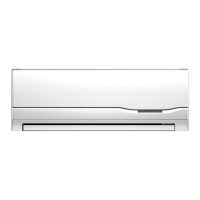
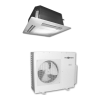
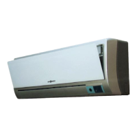
Details various functions of the indoor unit, including remote control, sensing, fan speed, and modes.
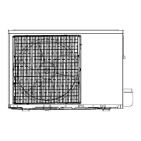
Highlights key operational features of the outdoor unit, such as power control and noise reduction.
Provides detailed dimensions for the indoor unit of the air conditioner.
Provides detailed dimensions for the outdoor unit of the air conditioner.
Illustrates the refrigerant flow diagram for cooling-only operation.
Shows the refrigerant flow diagram for heat pump mode, including reversing valve.
Defines the operational temperature ranges for effective cooling performance.
Defines the operational temperature ranges for effective heating performance.
Lists recommended torque values for installation fittings and connections.
Specifies requirements for connecting power and control cables.
Details maximum allowable pipe lengths and elevation differences for installation.
Describes the process of removing air from the refrigerant piping system.
Explains the procedure for recovering refrigerant during unit removal or re-installation.
Details the steps for purging air after re-installation or system modification.
Describes how to balance refrigerant levels using 2-way and 3-way valves.
Outlines the procedure for creating a vacuum in the refrigerant system.
Provides instructions for charging the refrigerant into the system.
Defines the meaning of various symbols and abbreviations used for electronic functions.
Lists and describes the various operational functions of the air conditioner.
Details the safety and protection features implemented in the electronic control system.
Explains the operation of the unit when only the fan is active.
Describes the operational characteristics and actions during cooling mode.
Outlines the functions and fan actions specific to dehumidifying operation.
Details the operations, fan actions, and protections during heating mode.
Explains the conditions, timing, and actions for defrosting operations.
Describes how the unit automatically selects operation mode based on temperature.
Explains the function to manually activate cooling operation.
Details the sleep mode function for enhanced comfort and energy saving.
Describes the unit's ability to resume operation after a power failure.
Explains the turbo mode for rapid temperature adjustment with high fan speed.
Explains the meaning and behavior of the operation and timer indicators.
Lists failure phenomena and their corresponding indicator status for cooling and heat pump modes.