Do you have a question about the Hokkaido HKEI-HCNI 353 XR and is the answer not in the manual?
| Brand | Hokkaido |
|---|---|
| Model | HKEI-HCNI 353 XR |
| Category | Air Conditioner |
| Language | English |
General safety instructions to prevent injury and property damage during operation and installation.
Critical warnings related to electrical shock, fire hazards, and improper handling during installation and operation.
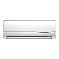
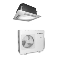
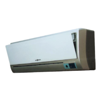
Details indoor unit functions like remote operation, fan control, sleep mode, auto mode, and timer settings.
Details outdoor unit functions like noise reduction, hydrophilic fins, 4-way valve control, and anti-rust cabinet.
Explains critical system controls like self-diagnosis, anti-cold wind, auto-defrost, and auto-restart capabilities.
Provides detailed dimensions (width, height, depth) for the HKEI 263-353-503 XR indoor units.
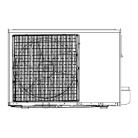
Shows dimensional drawings and measurements for the HCNI 263 XR outdoor unit.
Shows dimensional drawings and measurements for the HCNI 353 XR and HCNI 503 XR outdoor units.
Lists cooling/heating capacity, input, EER, COP, and moisture removal for different models.
Details specifications for compressors, indoor/outdoor fan motors, and indoor/outdoor coils.
Provides dimensions for indoor/outdoor units and refrigerant piping requirements like length and level.
Illustrates the refrigerant flow path through the indoor and outdoor units, including key components and valves.
Shows the electrical wiring diagram for the indoor unit, detailing connections to the PCB, fan, sensors, and power supply.
Presents the wiring diagram for the HCNI 263 XR outdoor unit, including compressor, sensors, and module connections.
Displays the electrical wiring diagram for the HCNI 353 XR outdoor unit, showing component connections and PCB layout.
Provides the wiring schematic for the HCNI 503 XR outdoor unit, illustrating connections for the compressor, fan, and PCB.
Specifies installation torque values and power cord selection criteria for proper connections.
Details requirements for refrigerant pipe length, elevation differences, and additional refrigerant charging.
Step-by-step procedure for removing air from the refrigeration piping to ensure efficient operation.
Instructions for safely pumping down refrigerant during re-installation, including valve operations and pressure monitoring.
Procedure for purging air from the system during re-installation, involving charging cylinder and flare nut operations.
Method to balance refrigerant levels by operating 2-way and 3-way valves, ensuring correct charge.
Detailed process for evacuating the refrigerant system using a vacuum pump to remove moisture and air.
Instructions for charging the system with the correct amount of refrigerant using a charging cylinder.
Presents cooling and heating performance characteristics for the HKEI-HCNI 263 XR model.
Displays cooling and heating performance curves for the HKEI-HCNI 353 XR based on ambient and piping length.
Illustrates cooling and heating performance curves for the HKEI-HCNI 503 XR based on operating conditions.
Defines temperature sensor abbreviations (T1-T4) and explains indoor display icons.
Details protection functions for 263-353 XR models like compressor delay, sensor faults, and preheating.
Lists protection functions for 503 XR models, covering compressor temp protection and preheating.
Explains fan-only mode and cooling mode operations like anti-freezing and compressor frequency control.
Details outdoor unit current control, rating capacity test, and turbo function in cooling mode.
Covers drying mode operations and heating mode functions like anti-cold-wind and auto fan control.
Explains compressor frequency control, outdoor unit current control, and indoor heat exchanger protection in heating.
Describes the conditions for defrosting initiation and termination, and the sequence of actions during defrost.
Details auto mode, forced operation functions, and the action of the 4-way valve in various modes.
Explains timer functions, sleep mode operation, and the auto-restart feature after power failure.
Essential safety warning about discharging high voltage capacitors in the outdoor unit before maintenance.
Lists error codes (E0-E6, P0-P4) and their corresponding LED status for indoor unit fault identification.
Step-by-step troubleshooting for EEPROM parameter errors (E0) and communication protection (E1).
Guides for resolving zero-crossing (E2), fan speed (E3), and outdoor sensor errors (E5).
Troubleshooting steps for indoor sensor (E6), IGBT over-current (P0), and voltage protection (P1) errors.
Solutions for compressor top temperature protection (P2) and inverter drive errors (P4).
Instructions for checking resistance values of compressor, fan motors, and sensors using a multi-meter.
Specifies resistance values for checking the step motor windings with a multi-meter for specific models.
Provides R-T data for various temperature sensors (T1-T4, Te) and resistance values at different temperatures.