Do you have a question about the Holip HLP-A100 Series and is the answer not in the manual?
Crucial safety steps before energizing the inverter to prevent damage or injury.
Safety guidelines for handling the inverter during the initial power-up sequence.
Precautions to ensure safe operation and prevent hazards while the inverter is running.
Safety measures and waiting periods required after the inverter has been powered down.
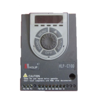
Explains the meaning of labels and codes on the inverter's type plate for identification.
Details specific technical parameters and models of the HLP-A100 series inverters.
Lists comprehensive technical data for power supply, motor, control functions, and applications.
Important checks to perform on the inverter and accessories before starting the installation process.
Provides physical dimensions and mounting details for the LCP and the inverter unit.
Presents detailed dimensions and frame sizes for various inverter models.
General guidelines and precautions for safe electrical installation, including cabling and regulations.
General guidelines and precautions for safe electrical installation, including cabling and regulations.
Specifies fuse ratings and main circuit terminal types for different inverter models.
Details proper mounting orientations and spacing for single and side-by-side installations.
Identifies and describes the main circuit terminals for power input and output connections.
Identifies and describes the main circuit terminals for power input and output connections.
Details the I/O control terminals, including digital, analog, and relay connections for different models.
Provides a basic connection diagram for the HLP-A100 series inverter, illustrating wiring practices.
Describes the components and functions of the Local Control Panel (LCP) operator interface.
Guides users on efficiently setting parameters using the LCP, including specific examples.
Step-by-step instructions for setting reference values using the LCP.
Explains how to interpret the FWD/REV status indicators and relate them to motor running direction.
Shows how to read various operational data items like frequency, current, and voltage from the LCP.
Instructions on how to access and view recorded alarms and fault codes for troubleshooting.
Guides on viewing the current status of various parameters like input/output terminals and operating states.
Explains the meaning of characters and symbols displayed on the inverter's LED segments.
Overview of parameters related to general operation settings and display options.
Lists parameters for configuring motor characteristics, load types, and adaptation settings.
Details parameters for configuring DC brake, AC brake, and mechanical brake functions.
Parameters for setting speed references, ramp times, and acceleration/deceleration profiles.
Parameters for setting operational limits, warnings, and fault conditions for motor speed and current.
Parameters for configuring digital inputs, digital outputs, and relay functions for external control.
Parameters for configuring analog input and output signals for voltage, current, and other measurements.
Parameters for setting up PI controllers for torque and process control loops.
Parameters for communication settings via RS485, Modbus, and FC port configurations.
Parameters for configuring Simple PLC functions, including order and parallel execution modes.
Parameters for special functions like switching frequency, overmodulation, and mains imbalance detection.
Provides read-only information about the drive's operating data, status, and identification.
Read-only parameters for viewing control word, reference values, status words, and active set-ups.
Parameters for cascade control, including mode, pressure settings, and frequency management.
Parameters for configuring the wobble function, including start modes, frequency, and length settings.
Details specifications for optional braking resistors, including model and suitable motor ratings.
Information on the external LCP mounting kit and installation steps for the LCP.
Guidelines for correct EMC installation to meet international standards and ensure optimal performance.
Lists all possible warnings, alarms, and errors, along with their descriptions and potential causes.
Provides guidance on diagnosing and troubleshooting common motor and system faults when no specific message is displayed.
General notes and checks to perform before conducting inspection and maintenance on the inverter.
Recommendations for proper storage and transport conditions to maintain inverter integrity.
Outlines the communication format specification for Modbus RTU protocol.
Details coil addressing, function codes, and data structures used in communication.
Explains how to read coil status, including transmit and receive data formats and examples.
Details how to read holding registers, including transmit, receive data, and examples.
Explains how to force single coil values to RAM and EEPROM with transmit/receive examples.
Demonstrates how to preset single register values with transmit/receive examples.
Provides examples for transmitting and receiving multiple coils for frequency and control word operations.
Shows an example of setting multiple registers, including transmit and receive data for C03.03.
Illustrates how to read/write array data, providing transmit and receive examples for parameters.
Lists communication exception codes and their descriptions, including format and content.
| Control Mode | V/F Control, Sensorless Vector Control |
|---|---|
| Cooling Method | Forced Air Cooling |
| Storage Temperature | -20°C to +60°C |
| Output Voltage | 0-Input Voltage |
| Overload Capacity | 150% for 60 seconds |
| Braking Unit | Built-in |
| Communication | Modbus RTU |
| Protection Functions | Overcurrent, Overvoltage, Undervoltage, Overheat, Overload |
| Efficiency | ≥98% |
| Operating Temperature | -10°C to +40°C |
| Humidity | 5% - 95% (non-condensing) |
| Altitude | ≤1000m (derating above 1000m) |
| Input Voltage | 3-phase 380V - 480V |
| Output Frequency | 0Hz - 400Hz |
| Frequency Range | 0Hz - 400Hz |