Do you have a question about the Holip HLP-NV Series and is the answer not in the manual?
Verifies inverter condition, packaging, and included items upon receipt.
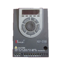
Explains the information provided on the inverter's nameplate for identification.
Crucial safety steps to follow before applying power to the inverter for installation.
Safety guidelines to observe when initially powering up the inverter.
Safety measures to adhere to while the inverter is operating.
Safety considerations for handling the inverter after it has been powered down.
Lists specific technical details and models of the HLP-NV series inverters.
Details general electrical, control, and environmental specifications for the inverter.
Guidelines for proper storage of the inverter to maintain its condition and performance.
Recommendations for selecting an appropriate location and environment for inverter installation.
Instructions on how to physically install the inverter, including orientation and spacing.
Illustrates the schematic for connecting the main power circuit of the inverter.
Details the arrangement and function of the inverter's main and control circuit terminals.
Provides a general wiring diagram for connecting the inverter's main and control circuits.
Explains the function of various switches on the inverter for configuration and bus termination.
Outlines critical safety precautions and best practices for wiring the inverter.
Introduces the LCP digital operator, its components, and displays.
Guides users on how to navigate menus and program parameters using the LCP.
Overview of parameters related to inverter operation states and display settings.
Parameters concerning motor characteristics, control principles, and load settings.
Parameters for configuring braking functions, including DC brake and energy braking.
Parameters for setting speed references, limits, and acceleration/deceleration ramps.
Configuration of digital input and output functions for control signals and status.
Settings for analog inputs and outputs, including scaling and signal types.
Parameters for configuring Proportional-Integral (PI) control loops for process applications.
Settings for communication protocols, baud rates, and address configuration.
Parameters for special inverter functions like switching frequency and mains monitoring.
Parameters for entering motor nameplate data such as power, voltage, and current.
Advanced motor data parameters for optimizing inverter performance.
Parameters related to the functionality of the LCP keypad and its operating modes.
Settings for motor parameters that are independent of the load condition.
Parameters for adjusting motor settings based on load conditions.
Parameters for configuring various start functions and timing for the motor.
Parameters for configuring different stop functions and their behavior.
Parameters for monitoring and protecting the motor based on estimated temperature.
Parameters for setting up the DC braking function to slow down or hold the motor.
Configuration of brake energy functions, including resistor and AC braking.
Parameters for controlling an external mechanical brake based on motor speed or faults.
Defines the range, minimum, and maximum values for speed references.
Settings for selecting and configuring various reference sources for speed control.
Selects the source for relative scaling of reference values for speed control.
Configuration of the first acceleration and deceleration ramp profiles.
Configuration of the second acceleration and deceleration ramp profiles.
Parameters for Jog and Quick Stop ramp functions.
Configuration of speed, torque, and current limits for motor operation.
Setting adjustable warning limits for current, speed, reference, and feedback.
Configuration to bypass specific speed ranges to avoid mechanical resonance.
Configuration of functions for the inverter's digital input terminals.
Configuration of timing and output functions for the inverter's relays.
Configuration of pulse input for frequency control and signal scaling.
Setup for analog input/output modes, including live zero timeout.
Configuration and scaling for analog input 1 (VIN).
Configuration and scaling for analog input 2 (AIN).
Configuration of the LCP potentiometer as a reference or relative reference source.
Configuration of analog output functions for signals like frequency or motor current.
Selection of feedback sources for Process PI Control.
Parameters for configuring the Process PI control loop.
Safety guidelines and precautions before performing inspection or maintenance.
Checks and tasks for regular inspection and maintenance of the inverter.
Guidance on identifying and resolving faults indicated by the inverter.
Detailed descriptions of fault codes and their corresponding disposal methods.
Provides mechanical drawings and dimensions for HOLIP NV inverter models.
Shows the physical dimensions for mounting the LCP digital operator.
Lists specifications for braking resistors, including power, resistance, and torque.
Steps to reset parameters to default settings and initialize the inverter.
How to use the LCP keypad for manual control and reference setting.
Instructions for controlling the drive using external terminals and AUTO mode.
Step-by-step guide for performing Automatic Motor Tuning (AMT).
How to configure and use speed up/down functions via digital inputs.
Configuration for selecting up to eight different speed presets using digital inputs.
Example setup for Process Closed Loop (PI) control with specific parameter settings.
Example configuration for using pulse input for frequency control and reference.
Examples of motor control principle settings for V/F and VVC+ modes.
Example of customizing the display to show motor speed.
Example of using LCP potentiometer for forward/reverse control and speed setting.
How to use LCP arrow keys for manual control and speed adjustment.
Practical examples of communication using FC and Modbus protocols.
User-configurable default settings for operation and display parameters.
User-configurable default settings for load and motor related parameters.
User-configurable default settings for brake functions.
User-configurable default settings for reference and ramp parameters.
User-configurable default settings for motor limits and warnings.
User-configurable default settings for digital input/output functions.
User-configurable default settings for analog input/output signals.
User-configurable default settings for Process PI control parameters.
User-configurable default settings for communication parameters.
User-configurable default settings for special inverter functions.
User-configurable default settings for drive information parameters.
User-configurable default settings for data readout parameters.