XL-FW482 Rev C · 2016-07-05 · Amendments and Errors Reserved · © SAF-HOLLAND, Inc., SAF-HOLLAND, HOLLAND, SAF,
and logos are trademarks of SAF-HOLLAND S.A., SAF-HOLLAND GmbH, and SAF-HOLLAND, Inc.
Installation Procedures
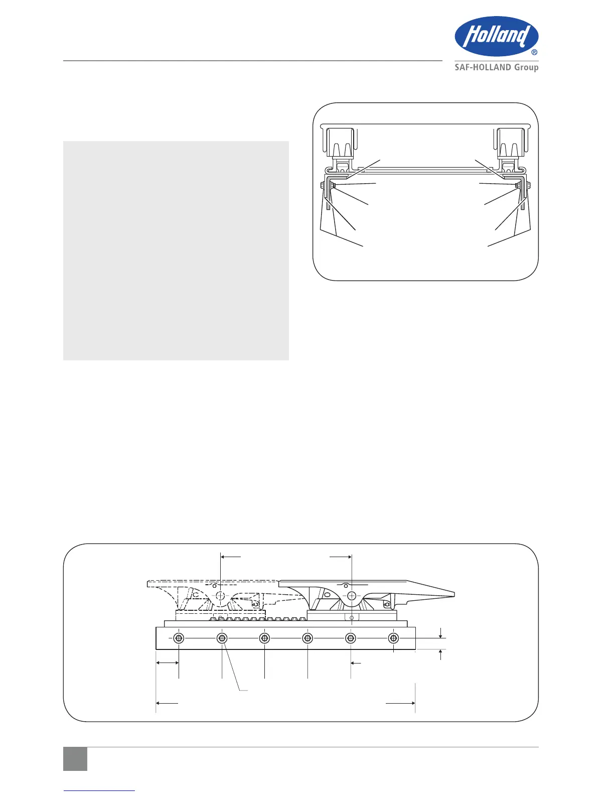
Figure 9
FORWARD TRAVEL
4.00"
(101.6 mm)
MAX
1.00"
(25.4 mm)
MIN
1" MIN. 6 BOLTS EQUALLY SPACED
PLATE LENGTH PLUS 2.00" MIN. (40.8 mm)
CENTER LINE OF
TRACTOR REAR
AXLE(S) OR BOGIE
5. Attach the slider plate and
mounting angles to the tractor
using recommendations in "General
Recommendations."
IMPORTANT: The full length of the fifth
wheel mounting angle should
seat flush on the truck frame
when mounting to prevent
flexing of mounting angle
and to give uniform weight
distribution along truck
frame rail (Figure 8 and 9).
IMPORTANT: Use 5/8" diameter Grade
8 bolts minimum size,
5/8" Grade C locknuts and
hardened steel washers or
flanged locknuts. Torque to
bolt manufacturer charts
(Figure 8 and 9).
6. Reassemble the fifth wheel top plate and
bracket sub-assembly to the slider base
plate if they were removed previously.
Figure 8
HARDENED STEEL WASHERS
REFER TO TABLE 1 FOR
MOUNTING ANGLE THICKNESS
5/8" GRADE 8 BOLTS
TRUCK FRAME RAIL
5/8" GRADE C LOCKNUTS
 Loading...