XL-FW482 Rev C · 2016-07-05 · Amendments and Errors Reserved · © SAF-HOLLAND, Inc., SAF-HOLLAND, HOLLAND, SAF,
and logos are trademarks of SAF-HOLLAND S.A., SAF-HOLLAND GmbH, and SAF-HOLLAND, Inc.
Installation Procedures
4.2 Outboard Angle Mounting
1. If angles are not installed, refer to
"Installation: General Recommendations,"
on page 4, for thickness and material.
Use 3" minimum horizontal and 3
1/2" minimum vertical leg size. Longer
horizontal legs may be required with
narrow frame widths. The recommended
length of each mounting plate is the same
length as the slide base mounting plate.
2. In addition to the information given in
"Installation: General Recommendations,"
on page 3, follow the recommendations
in Figure 10 and 11. The following
sequence is suggested:
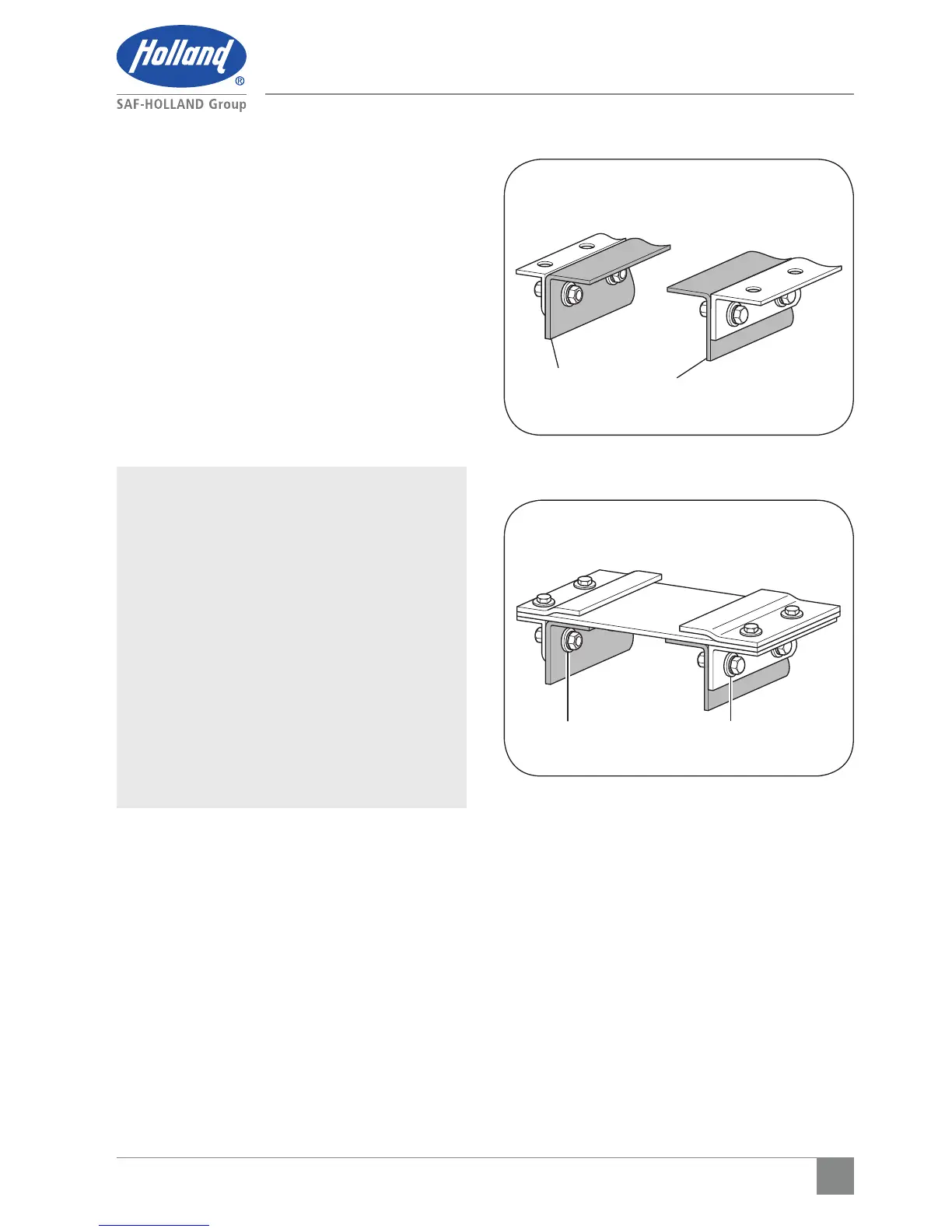
IMPORTANT: The full length of the fifth
wheel mounting angle should
seat flush on the truck frame
when mounting to prevent
flexing of mounting angle
and to give uniform weight
distribution along truck frame
rail (Figure 10).
IMPORTANT: Use 5/8" diameter Grade
8 bolts minimum size,
5/8" Grade C locknuts and
hardened steel washers or
flanged locknuts. Torque to
bolt manufacturer charts
(Figure 11).
a. Securely position the mounting
angles to the tractor frame and
attach as illustrated (Figure 10).
Follow the bolting recommendations
as illustrated (Figure 9). Angles
MUST be flush with the top of the
tractor frame.
b. Locate the slide base and center
left to right and front to rear on the
mounting angles. Clamp in place and
drill 21/32" diameter holes using
the mounting plate as a template if
holes are not provided in the angle.
Figure 10
Figure 11
TRACTOR FRAME
HARDENED STEEL WASHERS
 Loading...