1. Drain enough coolant out of the radiator to drop the coolant level below the point in which the engine coolant temperature
sensor is installed in the manifold.
2. Remove the sensor from the manifold and allow the sensor to reach room temperature, approximately 70° F.
3. Connect the positive (+) lead of a digital voltmeter set to measure resistance to the metal tab located at the top of the
sensor and the negative (-) voltmeter lead to the sensor’s body.
4. Measure the resistance. The resistance value of the temperature sensor at room temperature should be approximately 3.8
kΩ.
5. Submerse the body of the coolant temperature sensor in boiling water (212° F) and measure the resistance as described in
Step 3. The resistance value of the temperature sensor in boiling water should be approximately 182 kΩ.
NOTE: If the resistance values of your engine coolant temperature sensor do not match these values, the temperature sensor
must be replaced.
20.3 Testing the Throttle Position Sensor
A properly adjusted and functioning throttle position sensor is essential to the proper operation of the PRO-JECTION 2D system.
The TPS is a precision electrical component that acts as a variable resistor. The ECU provides a reference voltage to the TPS.
As the resistance varies with the throttle angle, the TPS provides a return signal to the ECU.
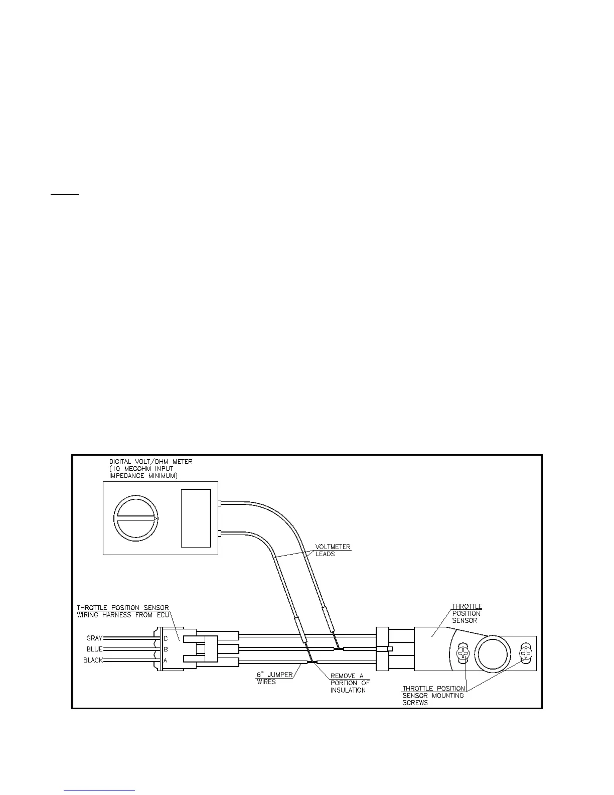
1. Disconnect the three-position connector from the TPS and install three jumper wires as shown in Figure 17.
2. Connect the positive (+) lead of a digital voltmeter set to measure DC voltage to the blue wire leading to the TPS and the
negative (-) lead of the voltmeter to the black wire leading to the TPS.
3. Turn the ignition key to the “RUN” position. Do not start the engine.
4. Observe the voltmeter and verify that the voltmeter indicates between 0.63 to 0.65 volts with the TPS set at idle.
5. Slowly open the throttle and observe the voltmeter’s readout. The voltage should increase smoothly from 0.63 volts at idle
to 4.5 to 5.0 volts at wide-open throttle. If the voltmeter readings fluctuate or seem jumpy, the TPS is intermittent and will
need to be replaced.
6. Remove the jumper wires and reinstall the 3-position connector.
Figure 17