Do you have a question about the Hologic DISCOVERY QDR Series and is the answer not in the manual?
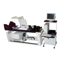
Provides an overview of the Hologic Discovery X-ray Bone Densitometer system and its capabilities.
Details the conceptual subsystems of the Hologic Discovery, including Operator's Console, Motor Control, and C-Arm Subsystems.
Lists technical specifications for the Discovery system, including scanning methods, X-ray system, detector system, and scan regions.
Describes the computer system and its role in controlling the Discovery scanner's operations.
Explains the PCI Communications Controller Board's function in managing communications between the computer and scanner assemblies.
Details the Distribution Board's role in interconnecting system components and distributing power and signals.
Describes the Motor Controller Board, its function in driving stepper motors, and monitoring mechanism positions.
Details the TZ Drive Board's function for pedestal motors in A and SL models, including service switches and power.
Explains the Control Panel Controller Board's function in interfacing the operator control panel to the computer.
Describes the C-Arm Interface Board's role in distributing power and signals for C-Arm assembly devices.
Details the X-Ray Controller Assembly's function in providing pulsed power and control for the X-ray source unit.
Explains the Data Acquisition System's components and function for converting X-ray signals to digital data.
Describes the Data Acquisition System for A models, including its three main components and their locations.
Explains the Integrator/Multiplexor Board's role in integrating and storing signals before sending them to the ADC.
Details the Analog to Digital Board's function in converting analog signals to digital format for processing.
Describes the Torroid Power Module and DIN Rail's function in providing AC voltage to the system.
Lists required tools and documentation needed before installing the Discovery system.
Provides minimum room and doorway dimensions required for system installation.
Details the procedures for uncrating the system and moving it to its final installation location.
Describes how to remove the tabletop to fit through doorways if needed.
Provides instructions for removing the C-arm assembly for narrow hallways.
Details the process of moving the unit to its destination room, including using ramps.
Guides through the steps of setting up the unit after moving it to its final location.
Provides instructions for installing the C-arm assembly on C, Ci, W, and Wi models.
Details the procedure for installing the upper C-arm assembly on A and SL models.
Covers the final steps to install the system, including cabling and leveling.
Provides instructions for connecting the system's power and communication cables.
Explains how to measure and verify the input AC voltage for system operation.
Guides the installation of the computer system, including peripherals.
Details how to start the QDR software in service mode for configuration and testing.
Describes how to check and verify the alignment of the scanner table.
Provides steps for adjusting the front-to-back T-Rail dimensions and table edge-to-rail gap.
Details the procedure for adjusting C-arm parallelism on A and SL systems.
Covers the calibration and testing procedures for the Discovery system's core functions.
Explains how to check the X-ray tube's peak kV potential accuracy.
Provides the procedure for checking the X-ray tube current.
Details the steps for adjusting belt tension on various motors within the system.
Guides through the motor calibration process using the SQDRIVER program.
Crucial procedure for aligning the X-ray beam with the detector array for accuracy.
Procedure to locate and set aperture positions and centers, specific to certain models.
Describes how to adjust the laser for proper patient positioning and scan accuracy.
Explains how to adjust the A/D gain potentiometer for consistent detector input.
Procedure to verify lateral alignment of the system on A and SL models.
Details the process for checking the High Voltage Power Supply/Source for radiation leakage.
Covers the three-stage calibration process for Area, BMD, and BMC measurements.
Procedure for calibrating scan thickness measurement on C and W models.
Procedure for calibrating scan thickness measurement on A and SL models.
Details the calibration of AREA and BMC measurements for array scan modes.
Describes how to re-analyze AP scans and add them to the QC database after calibration.
Covers the installation and configuration of optional software features.
Guides through testing the system's functionality in various scan modes.
Procedure for measuring the X-ray dose delivered to the patient during scans.
Details how to measure X-ray scatter radiation using a phantom.
Tests the scanner's ability to perform consecutive scans with consistent results.
Specifies requirements for instruments performing Body Composition Analysis (BCA).
Defines requirements for instruments performing BMD Whole Body Analysis.
Procedure to check and verify the alignment of the scanner table.
Details how to adjust the parallelism of the C-arm assembly.
Crucial procedure to align the X-ray beam with the detector array for optimal performance.
Procedure to locate and set the exact starting positions of apertures (slits).
Guides through calibrating the system's motors (AY, AR, TY, TX, TZ) using SQDRIVER.
Details how to adjust the laser for correct patient positioning and scan accuracy.
Explains the adjustment of the A/D gain potentiometer for consistent detector input.
Procedure to align the filter drum encoder for accurate timing and operation.
Procedure to flatten the X-ray beam for each scan mode and find the table's metal edge.
Procedure to verify lateral alignment, specifically for QDR 4500A and SL systems.
Verifies X-ray beam alignment and uniformity across the tabletop for Discovery A and W models.
Procedure to compare scan results with actual phantom values for calibration verification.
Calibrates scan thickness measurement for C and W models using a phantom.
Calibrates scan thickness measurement for A and SL models using a phantom.
Calibrates AREA and BMC measurements for array scan modes after thickness calibration.
Re-analyzes AP scans and adds them to the QC database post-calibration.
Lists essential tools required for performing FRU removal and replacement procedures.
Describes how to remove and replace FRUs located in the Electronics Tray/Carriage Drive.
Provides steps for removing and replacing the C-arm Y Encoder.
Details how to remove and replace FRUs associated with the Table Y motion.
Instructions for removing and replacing the Control Panel assembly.
Guides on removing and replacing PCBs located under the right side of the table.
Provides steps for removing and replacing the Table Y-Belt.
Details how to remove and replace the Table Y Motor or Gearcase.
Provides instructions for removing and replacing the Table Y Encoder.
Describes how to remove and replace FRUs associated with the Table X motion.
Instructions for removing and replacing the TX Motor Controller board.
Provides steps for removing and replacing the Table X Belt.
Details how to remove and replace the Table X Motor or Gearcase.
Provides instructions for removing and replacing the Table X Encoder.
Describes how to remove and replace FRUs associated with Table Z motion.
Guides on removing and replacing the pedestal.
Details the installation and adjustment of the Linear Rotary String (Encoder).
Describes FRUs located on the lower C-arm, including boards and assemblies.
Instructions for removing and replacing the C-Arm Interface Board.
Provides steps for removing and replacing the X-Ray Controller (XRC) assembly.
Details the procedure for removing and replacing the Filter Drum Assembly.
Guides on removing and replacing the Tank Assembly, noting weight precautions.
Describes FRUs for Arm R (Rotate) motion on A and SL models.
Instructions for removing and replacing the Motor Controller Board.
Provides steps for removing and replacing the Arm R Belt.
Details removing and replacing the Arm R Motor, Gearcase, Encoder, or Belt.
Guides on removing and replacing the Gas Spring assembly.
Describes FRUs located on the upper C-arm, including detector and laser assemblies.
Instructions for removing and replacing the Detector Assembly on specific system models.
Details replacing older detector assemblies with newer ones on Ci and Wi systems.
Provides steps for removing and replacing the Laser or Laser Assembly.
Instructions for removing and replacing the ADC Board on A models.
Describes FRUs located on the Aperture Assembly.
Details removing and replacing the Aperture Stepper Motor.
Provides instructions for removing and replacing the Aperture Motor PCB.
Guides on removing and replacing the Aperture Position Belt.
Details removing and replacing the Rotary Potentiometer.
Describes FRUs located on the Drum Assembly.
Provides instructions for removing and replacing the Drum Encoder PCB.
Details removing and replacing the Drum Belts.
Guides on removing and replacing the Stepper Motor Assembly.
Details removing and replacing the Drum Bearings.
Provides instructions for replacing EMI cables, emphasizing proper grounding.
Provides lists of Field Replaceable Units (FRUs) for identification and ordering.
Guides for troubleshooting issues related to power supply and dead systems.
Provides suggestions for diagnosing and resolving issues with table and C-arm movement.
Troubleshooting steps for issues with the Control Panel response or functions.
Categorizes display issues (vertical stripe, horizontal stripe, noise, no display) and suggests checks.
Troubleshooting guidance for issues related to targeting and laser functionality.
Addresses issues occurring between the computer and the scanner related to data communication.
Troubleshooting common specification problems related to Area, BMD, BMC, and CV.
Lists common X-ray subsystem problems and suggested solutions.
Provides suggestions for when the X-ray beam does not align properly.
Troubleshooting steps for when the system consistently fails the detector flattening procedure.
Guidance for troubleshooting issues related to the laser system's operation.
Instructions for addressing oil leaks, focusing on torque specifications for tank cover.
Lists common miscellaneous problems and their corresponding solutions.
Outlines recommended daily and weekly maintenance tasks for the customer.
Lists annual and semi-annual preventive maintenance procedures for trained service personnel.
Details the cleaning and greasing procedures for guide rails and bearings.
Summarizes PCB components, LEDs, voltage sources, and jumper settings for the Distribution Board.
Summarizes PCB components, jumpers, and refer-to information for the PCI Communications Command Board.
Details PCB components, signals, sources, jumpers, and refer-to info for Stepper Motor Controllers.
Summarizes PCB components, LEDs, voltage sources, and jumpers for the TZ Drive Board.
Summarizes PCB components, voltage, source, and jumpers for the 128-Channel Detector Assembly.
Summarizes PCB components, source, and refer-to info for the Detector Array Assembly.
Summarizes PCB components, voltage, source, jumpers, and refer-to info for the ADC Board.
Summarizes PCB components, signals, voltage sources, and jumpers for the C-Arm Interface.
Describes the X-Ray Survey utility for testing X-ray generation and detection functions.
Provides instructions on how to launch the X-Ray Survey utility.
Explains the components and data presentation within the X-Ray Survey Main Display.
Details the various controls within the X-Ray Survey display.
Describes the SQDRIVER program for motor calibration and troubleshooting.
Explains the SQVERIFY program for performing low-level system component tests.
Describes the SQKEYPAD program for manual motor control and checking functions.
Lists system error messages, their hardware/software classification, locus, and recommended action.
| Type | Bone Densitometer |
|---|---|
| Power Requirements | 100-240 VAC, 50/60 Hz |
| Scan Time | Approximately 10 seconds for a spine scan |
| Applications | body composition analysis |
| Body Composition Analysis | Yes, including fat and lean mass measurements |
| Software | Hologic APEX Software |
| Scan Regions | Spine, hip, forearm, whole body |
| X-ray Source | Dual-energy X-ray source |
| Detector Type | Digital detector array |
| Scan Modes | Fast |


