Do you have a question about the Hologic DISCOVERY C and is the answer not in the manual?
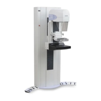
Hologic Discovery® X-ray Bone Densitometer estimates bone mineral content and density using dual-energy X-rays.
Describes the X-ray source, fan beam, and detector array used in the scanning process.
Details the technical specifications of the Discovery X-ray Bone Densitometer system.
Describes the computer's role in controlling scanner movement, X-ray generation, and database management.
Handles communications between the PC and scanner assemblies, connecting via a ribbon cable.
Provides interconnections between the Operator's Console and scanner, distributing signals and DC power.
Lists necessary tools for installing the Discovery system, including screwdrivers, pliers, and measurement tools.
Lists necessary tools for installing the Discovery system, including screwdrivers, pliers, and measurement tools.
Lists required documents for installation, including Radiation Measurement Report and FDA Form 2579.
Provides minimum room and doorway dimensions for SL, C, A, and W models.
Outlines procedures for uncrating the system and preparing it for transport.
Provides steps for setting up the unit after moving it to the destination room.
Outlines the process of cabling the system after physical installation.
Guides the installation of AC input cables, circuit breakers, and mounting hardware.
Ensures the system is powered from a dedicated power line and checks voltage.
Outlines the procedure to check the table's alignment using a measuring tape.
Outlines procedures for calibrating and testing system components, starting with kV peak potential.
Explains how to check X-ray tube peak potential using an oscilloscope and voltage divider.
Details the procedure to check X-ray tube current using an oscilloscope and barrier strip.
Uses SQDRIVER program to calibrate motors (AY, AR, TY, TX, TZ) and determine motion limits.
Crucial procedure to align X-ray beam with detector array for repeatability, using an alignment fixture.
Ensures consistent input to ADC converter by adjusting potentiometer, depending on system configuration.
Checks average X-ray signal level and detector range before any A/D gain adjustment.
Adjusts A/D gain potentiometer for average X-ray signal of 6.25V and checks detector range.
Flattens X-ray beam for each scan mode and finds the metal edge of the table.
Checks for radiation leakage from the HVPS/S at installation or after repair.
Calibration in three stages: Scan Thickness, Area/BMC, and Adding AP scans.
Measures radiation dose using a Victoreen meter during installation and service.
Measures scatter radiation using a survey meter at installation.
Checks table alignment by measuring distances to T-rails and rail gaps.
Provides procedures to align the table based on measurements from the alignment check.
Details adjusting the "A" dimension by modifying pedestal bolts.
Adjusts front-to-back T-Rail dimensions and table edge-to-rail gap.
Measures and adjusts C-arm parallelism using a digital level and tank cover removed.
Crucial procedure to align X-ray beam with detector array for repeatability, using an alignment fixture.
Calibrates motors (AY, AR, TY, TX, TZ) using SQDRIVER to determine motion limits.
Procedure to calibrate the TZ motor driver, moving pedestals to mechanical limits.
Procedure for calibrating the AY motor, including checking position value and linear fit.
Procedure for calibrating the TY motor on A, W, and Wi models, including left/right mechanical stops.
Ensures consistent input to ADC converter by adjusting potentiometer, depending on system configuration.
Calibration in three stages: Scan Thickness, Area/BMC, and Adding AP scans.
Describes removing and replacing FRUs in the Electronics Tray/Carriage Drive area.
Describes removing and replacing FRUs associated with Table Y motion.
Describes removing and replacing FRUs associated with Table X motion.
Describes removing and replacing FRUs associated with Table Z (up/down) motion.
Describes FRUs on the lower C-arm: C-Arm Interface Board, X-Ray Controller, Tank, Filter Drum, Arm rotation.
Provides instructions for removing and replacing the Tank Assembly, noting its weight.
Describes FRUs on the upper C-arm: Detector Assembly, ADC Board, Control Panel, Laser Assembly.
Describes FRUs on the Aperture Assembly.
Describes FRUs on the Drum Assembly.
Ensures software configuration is compatible with the scanner before troubleshooting.
Provides a table of power component locations and troubleshooting steps for dead systems.
Addresses failures related to table and C-arm movement, suggesting checking error logs and identifying the bad axis.
Categorizes display issues into vertical stripe, horizontal stripe, noise, and no display.
Recommends annual or semi-annual procedures for trained service personnel.
32-bit utility testing X-Ray generation and detection, used by Hologic engineers.
Controls that affect data display, categorized into X-Rays, Test Signals, Display, and Status Bits.
Program accessed via Utilities|Service Utilities|SQDRIVER; used for motor calibration and troubleshooting.
Diagnostic program for low-level tests of system components; refer to SQCHECK User Manual.
| Brand | Hologic |
|---|---|
| Model | DISCOVERY C |
| Category | Medical Equipment |
| Language | English |