Discovery QDR Series Technical Manual
2-6
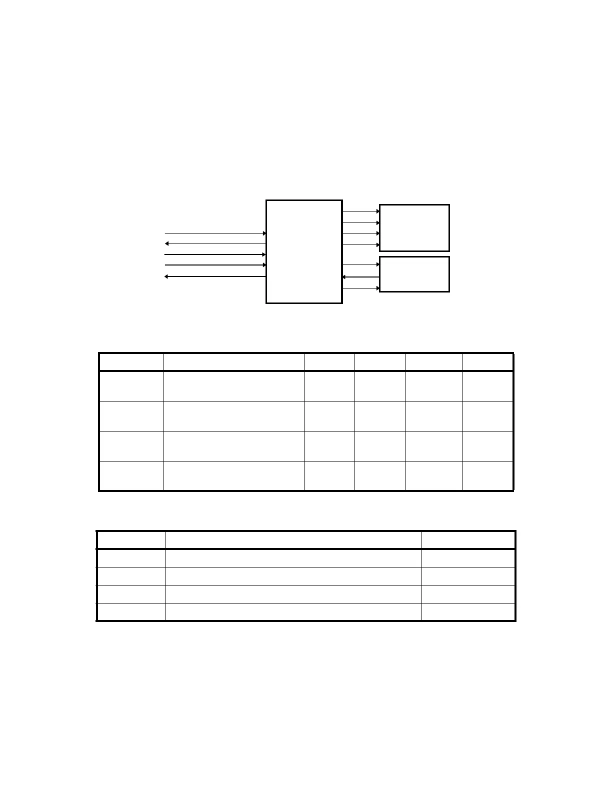
2.4.2 Interface Connections
Figure 2-3 shows the typical interconnections between the Distribution Board, the Motor
Controller Board, the Stepper Motor, and the Position Encoder. Figure 2-1 describes the
interconnections between the Distribution Board and the Motor Controller. Table 2-3
describes the interconnections between each Motor Controller and its respective stepper
motor and position encoder. The tables also identify the connectors and their pin
assignments.
Figure 2-3. Distribution Board/Motor Controller Board Interconnection Diagram
Table 2-2.Distribution Board/Motor Controller Board Interconnection Descriptions
Table 2-3. Motor Controller Board/Stepper Motor and Position Encoder
Interconnection Descriptions
2.5 TZ Drive Board (A and SL Only)
The TZ Drive Board is a microprocessor-controlled power driver circuit for the two AC
pedestal motors, which raise and lower the patient table of the Discovery A and SL. This
Signal Description Table X Table Y C-Arm Y Pin(s)
ARD+
ARD-
Asynchronous Receive Data. JP7 JP5 JP11 11
12
ATD +
ATD -
Asynchronous Transmit Data. JP7 JP5 JP11 14
15
SYSRST+
SYSRST-
System Reset. Resets the Motor
Controller Board.
JP7 JP5 JP11 17
18
28V
28V_RET
DC power for the Motor
Controller Board.
JP7 JP5 JP11 2,3,4,5
1,6,7,8
Signal Description Pin
(No label) Motor drive signals (4). JP5-1 - JP5-4
+REF (+3V) Precision positive voltage to position potentiometer. JP3-1
(No label) Position encoder wiper return voltage. JP3-3
-REF (-3V) Precision negative voltage to position potentiometer. JP3-5
ARD+, ARD-
ATD+, ATD-
SYSRESET+, SYSRESET-
+28V
28V_RET
(
⎯
)
(
⎯
)
(
⎯
)
(
⎯
)
+REF
(
⎯
)
-REF
MOTOR
STEPPER
MOTOR
To/From
Distribution Board
POSITION
ENCODER