Do you have a question about the Hologic DISCOVERY W and is the answer not in the manual?
Details the X-Ray Controller Assembly function and its interface connections to the C-Arm Interface Board.
Describes the X-Ray Source Unit (Tank) assembly, its components, and interconnections.
Lists essential tools and documentation required before installing the Discovery system.
Instructions for uncrating the system, inspecting for shipping damage, and moving it to its final location.
Guides on taking inventory of shipped items and measuring the transport path to the destination room.
Steps to prepare the tabletop for movement and procedures for moving the unit to its destination.
Procedures for setting up the unit after moving it to the destination room.
Detailed steps for installing the C-arm assembly on C, Ci, W, and Wi models.
Detailed steps for installing the upper C-arm assembly on A and SL models.
Guides on installing the system and connecting necessary cables, including voltage selection.
Instructions for checking and measuring the AC voltage at the outlet and transformer secondary.
Procedure for checking the table alignment by measuring distances and gaps.
Procedure for adjusting C-Arm parallelism using a digital level.
Procedure to check table alignment by measuring distances and gaps.
Detailed procedures for aligning the table, including edge-to-T-rail adjustments.
Procedure for adjusting C-Arm parallelism using a digital level.
Crucial procedure to align the X-ray beam with the detector array for optimal repeatability.
Locates and centers each aperture (slit) in motor steps, saving positions in HARDWARE.INI.
Calibrates motors (AY, AR, TY, TX, TZ) using SQDRIVER, setting encoder readback and motion limits.
Procedure for calibrating the AY motor, including checking position value and linear fit.
Procedure for calibrating the TY motor, including checking position value and linear fit.
Procedure for calibrating the TX motor, including checking position value and linear fit.
Procedure for calibrating the AR motor, including checking table level and C-arm angles.
Adjusts the laser positioning to ensure correct C-Arm positioning over the patient.
Procedure to align the filter drum encoder using oscilloscope and specific test points.
Procedure to flatten the X-ray beam for each scan mode and find the table's metal edge.
Procedure to verify lateral alignment of the system for A and SL models.
Covers scan thickness, area/BMC calibration, and adding AP scans to the QC database.
Describes FRUs in the Electronics Tray and ESD precautions for handling components.
Procedure for removing and replacing FRUs like Distribution Board, Motor Controller Board, etc.
Procedure for removing and replacing the TX Motor Controller board.
Procedure for removing and replacing either pedestal.
Details the installation and adjustment procedures for the Linear Rotary String (Encoder).
Describes FRUs for the lower C-arm, including C-Arm Interface, X-Ray Controller, Tank, and Filter Drum Assemblies.
Procedure for removing and replacing the X-Ray Controller (XRC).
Procedure for removing and replacing the Tank Assembly, noting its weight.
Procedure for removing and replacing the Detector Assembly on A, SL, W, C systems.
Procedure for replacing older detector assemblies with new ones on Ci and Wi systems.
Identifies locations of power components and provides troubleshooting suggestions for power issues.
Troubleshooting guide for table and C-arm movement issues, including checking error logs.
Categorizes display issues (vertical stripe, horizontal stripe, noise, no display) and provides troubleshooting steps.
Troubleshooting steps for missing scan display, white/dark screen, or blotchy display.
Troubleshooting data communication issues between the computer and the scanner.
Lists common X-ray problems and suggested solutions, including 'No X-Rays'.
Troubleshooting steps when the X-ray beam does not align properly per the procedure.
Steps to take when the system fails X-ray beam alignment verification.
Troubleshooting steps when the system consistently fails the detector flattening procedure.
Troubleshooting guidance for laser issues, including safety precautions and potential causes.
Lists annual/semi-annual procedures for service personnel, including backups, file maintenance, and checks.
Overview of the X-Ray Survey utility for testing X-ray generation and detection functions.
Used for motor calibration and troubleshooting motor movement problems.
Diagnostic program for performing low-level tests of system components.
C-arm and table are too close; check calibration or mechanical stops.
Errors related to reversed motor direction, hitting limits, or collision detection.
Errors indicating X-ray controller timing interrupt issues or incorrect firing order.
Error when X-ray signal level does not match filter drum position, indicating potential sync issues.
| Brand | Hologic |
|---|---|
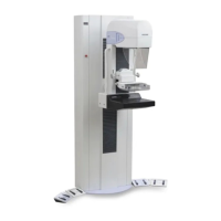
| Model | DISCOVERY W |
| Category | Medical Equipment |
| Language | English |