Discovery QDR Series Technical Manual
Table of Contents iii
Chapter 1 -
INTRODUCTION
1.1 System Overview ............................................................................................... 1-1
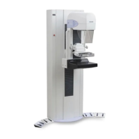
1.1.1 X-Ray Scanning Principles ....................................................................... 1-2
1.2 Functional Overview .......................................................................................... 1-4
1.3 Product Specifications ..................................................................................... 1-10
1.3.1 Exam Mode(s) Performance ................................................................... 1-12
1.3.2 Duty Cycle: ............................................................................................. 1-13
1.3.3 Leakage Technique Factors .................................................................... 1-13
1.3.4 Minimum Beam Filtration ...................................................................... 1-13
1.3.5 Measured Half Value Layer (HVL) At Different Operating Potentials . 1-13
1.3.6 Line Voltage and Maximum Line Current ............................................. 1-13
1.3.7 Technique Factors for Maximum Line Current ...................................... 1-13
1.3.8 Maximum Deviation ............................................................................... 1-14
1.3.9 Measurement Criteria for Technique Factors ......................................... 1-14
Chapter 2 -
FUNCTIONAL DESCRIPTION
2.1 Computer ........................................................................................................... 2-1
2.2 PCI Communications Controller Board ............................................................. 2-1
2.2.1 Interface Connections ............................................................................... 2-1
2.3 Distribution Board ............................................................................................. 2-3
2.3.1 Power ........................................................................................................ 2-3
2.3.2 Interface Connections ............................................................................... 2-4
2.4 Motor Controller Board ..................................................................................... 2-5
2.4.1 Power ........................................................................................................ 2-5
2.4.2 Interface Connections ............................................................................... 2-6
2.5 TZ Drive Board (A and SL Only) ...................................................................... 2-6
2.5.1 Service Switches ....................................................................................... 2-7
2.5.2 Power ........................................................................................................ 2-7
2.5.3 Interface Connections ............................................................................... 2-8
2.6 Control Panel Controller Board ....................................................................... 2-10
2.6.1 Power ...................................................................................................... 2-10
2.6.2 Interface Connections ............................................................................. 2-10
2.7 C-Arm Interface Board .................................................................................... 2-12
2.7.1 Continuity Daisy Chain .......................................................................... 2-13
2.7.2 Power ...................................................................................................... 2-13
2.7.3 Interface Connections ............................................................................. 2-13
2.8 X-Ray Controller Assembly (P/N 010-1273) .................................................. 2-16
2.8.1 Interface .................................................................................................. 2-16