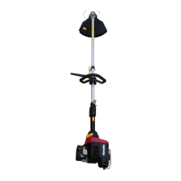
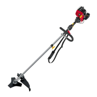
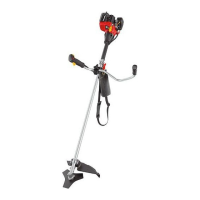
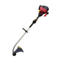
DESCRIPTION
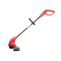
1. CUTTING LINE 40. OPENING IN REAR HOUSING
2. GRASS DEFLECTOR 41. MOUNTING BRACKET
3. LINE CUT-OFF BLADE 42. NOTCHES
4. ENGINE HOUSING 43. LOCKING TABS
5. STARTER GRIP 44. THREADED MOUNTING
6. THROTTLE TRIGGER PLATES
7. STRAP HANGER 45. SPANNER (16 mm)
8. SHOULDER STRAP 46. DRIVE CONNECTOR
9. KNOB 47. SPOOL RETAINER
10 BLADE GUARD 48. STRING HEAD
11. TRI-ARC BLADE 49. HOLDING PIN
12. GEAR HEAD 50. UPPER FLANGE WASHER
13. SHAFT 51. SPANNER (13 mm)
14. COUPLER 52. BLADE NUT
15. FRONT "J" HANDLE 53. CUPPED WASHER
16. IGNITION SWITCH 56. PRIMER BULB
17. THROTTLE INTERLOCK 57. WARM START POSITION
18. EXTENSION SHAFT 58. COLD START POSITION
19. GUIDE RECESS 59. LEVER
20. POSITIONING HOLE 60. SPRING
21. HANGER CAP 61. SLOTS
22. HOLE 62. EYELETS
23. BUTTON 64. SPOOL
24. BOLT 1/4 -20 x 1 in. 65. ARROWS ON SPOOL
25. BOLT 1/4 -20 x 1 1/2 in. 66. ANCHOR HOLE
26. SPACER 67. FIRST STRING
27. FLAT WASHER 68. SECOND STRING
28. LOCK WASHER 69. CLIPS
29. HEX NUT 70. BLADE PROTECTOR
30. BOTTOM CLAMP 71. PULL COVER TO OPEN
31. TOP CLAMP 72. FILTER
32. QUICK RELEASE TAB 73. AIR FILTER COVER
33. LATCH 74. IDLE SPEED SCREW
35. REAR HOUSING 75. LO NEEDLE
36. SILENCER GUARD 76. HIGH NEEDLE
37. SCREWS
38. TORQUE WRENCH
39. BENT END OF SILENCER
GUARD
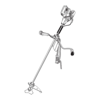
ASSEMBLY
ATTACHING THE POWER HEAD TO THE
TRIMMER ATTACHMENT (Fig. 2)
WARNING
Never attach or adjust any attachment while
power head is running. Failure to stop the engine
may cause serious personal injury.
The trimmer attachment connects to the power head by
means of a coupler device.
■ Loosen the knob (9) on the coupler (14) of the power
head shaft (13) and remove the end cap from the
attachment.
■ Push in the button located on the trimmer attachment
shaft. Align the button with the guide recess on the
power head coupler and slide the two shafts together.
Rotate the trimmer attachment shaft until the button
locks into the positioning hole.
NOTE: If the button does not release completely in
the positioning hole, the shafts are not locked into
place. Slightly rotate from side to side until the button
is locked into place.
■ Tighten the knob securely.
WARNING
Be certain the knob is fully tightened before
operating equipment; check it periodically for
tightness during use to avoid serious injury.
REMOVING THE ATTACHMENT FROM THE
POWER HEAD
For removing or changing the attachment:
■ Loosen the knob.
■ Push in the button and twist the shafts to remove and
separate ends.
ATTACHING THE STORAGE HANGER (Fig. 3)
There are two ways to hang your attachment for storage.
■ To use the hanger cap (21), push in the button and
place the hanger cap over end of the lower end
attachment shaft. Slightly rotate the cap from side to
side until the button locks into place.
■ The secondary hole (22) in the attachment shaft can
also be used for hanging.
FRONT HANDLE (Fig. 4)
A barrier handle should be used for ensuring the best
control and maximising operator safety.
■ Hold the top (31) and bottom clamp (30) snugly in
position on the shaft housing so that handle will be
located to the operator’s left.
■ Insert the end of the handle between the clamps.
■ Align the bolt holes and push the long bolt (1/4-20 x
1 1/2 in) (25) through the handle side.
■ Place short bolt (1/4-20 x 1 in) (24) through opposite
side of clamp. Install flat washer (27), lock washers
(28) and hex nuts (29) to hold the assembly in place.
■ After assembly is complete, adjust the position of the
handle for best balance and comfort.
■ Tighten first the long bolt and then the short bolt.
■ Connect the shoulder strap to the strap hanger (7)
and adjust to a comfortable position.
 Loading...