1
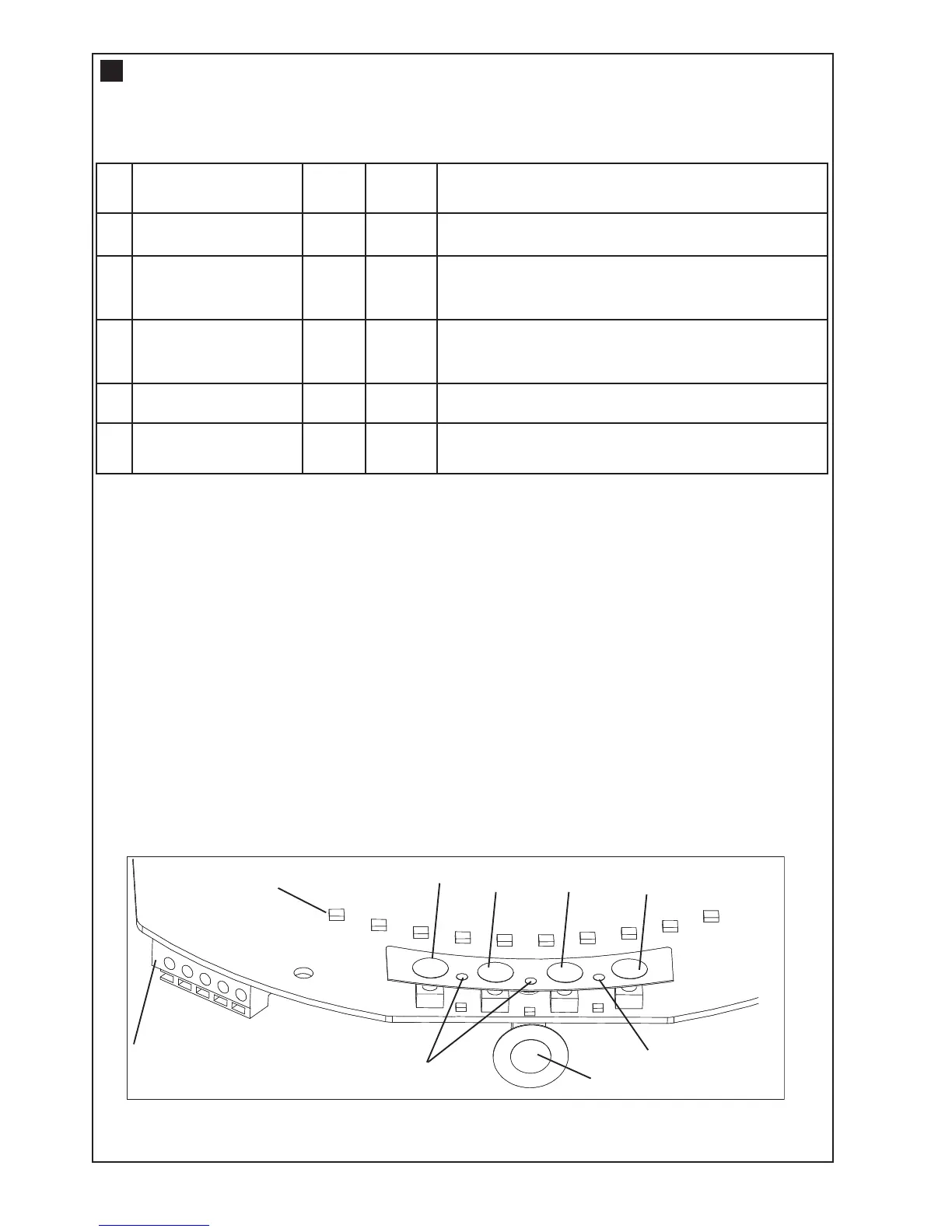
. Terminal Block: used for external accessories (see chart below).
NOTE: The terminal block is behind a plastic cover in the back housing. Use a small screwdriver to lever
open the plastic cover if access to the terminal block is required. All wires should be secured appropriately.
2. DN Button: used to drive door DOWN.
3. UP Button: used to drive door UP.
4. P Button: used to “PROGRAM” the DOOR LIMITS.
5. S Button: used to “SAVE” the “REMOTE CONTROLS”.
6. LEDs: 1. Program DOWN, and Diagnostic code indicator Number 1.
2. Program UP indicator.
3. Diagnostic code indicator Number 2
7. Control Button: Used to activate the door when remote controls are not available. Open - Stop - Close.
8. Courtesy Light: turns on during operation and automatically turns off after 3 minutes.
No Function
Colour
Polarity Comment
1
Push button
Red
+ve
Dry contact input for push button wired wall
c
ontrols:
2
C
ommon
White
-
ve
Common terminal for push button, obstruction
detection beams & accessory power:
2 Common White -ve Common terminal for push button, IR Beam &
accessory power:
3 Obstruction Detection
Beams
Grey
+ve
IR Beam Input: (pulsing type only)
4
Accessory Power
Green
+ve
24v dc 50 mA accessory output available for a
universal receiver
C
ONTROL PANEL
4