EasyManua.ls Logo

HON Initiate Flexconnect User Manual

HON Initiate Flexconnect
3 pages
To Next Page IconTo Next Page
Page #1 background imageLoading...
Page #1 background image
INSTALLATION IINSTRUCTIONS
Initiate™
Flexconnect
TM
ELECTRICAL SSYSTEM ((8-wwire)
42-2241
SIDE 1 OF 3 (7/01)
Connection to a power source, by a licensed electrician, and quantity of receptacles used for a given cir-
cuit must be in compliance with all national and local electrical codes. Connect a maximum of 13 recep-
tacles (12 in Canada, and fewer in certain U.S. locales) to one circuit. Consult applicable national and
local electrical codes.
Disconnect electrical connections between panels prior to removal of a mechanical connection. Ensure
that the power supply is disconnected prior to disconnecting any electrical components.
When electrical components are interconnected from one panel to another, the panels must be mechan-
ically connected per the appropriate panel-to-panel installation instructions.
Failure to observe these warnings could result in a fire or electrical shock.
WARNING
Illustration 1. General Configuration and Component Identification:
Illustration 2. Electrical Wiring Diagrams:
Component Identification: Color of terminal ends and
receptacle backs are BLACK.
Component Identification: Color of terminal ends and
receptacle backs are RUST.
Power harness (24")
871224
Power harness
(30"-60") 8712XX
Notes: All electrical components
are UL Listed to UL1286
and UL183.
By pulling on terminal
housing at end of cable
assemblies, Power and
Pass-Thru harnesses can
be stretched up to 3
1
/
2
"
.
4 hot / 2 neutral / 2 ground systems:
color of terminal ends are black.
3 hot / 3 neutral / 2 ground systems:
color of terminal ends are rust.
Pass-Thru harness (24"-60")
8711XX
Pass-Thru cable (12"-18")
8710XX
Connect to previously installed cable.
Stretch, as required, to proper position.
Snap onto mounting bracket.
Question and Answer IconNeed help?

Do you have a question about the HON Initiate Flexconnect and is the answer not in the manual?

HON Initiate Flexconnect Specifications

General IconGeneral
CategoryIndoor Furnishing
BrandHON
CollectionInitiate
MaterialFabric, Mesh, Plastic, Metal
AdjustabilitySeat Height, Tilt Tension, Tilt Lock, Arm Height (some models)

Summary

General Configuration and Component Identification

Power and Pass-Thru Harnesses

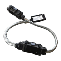
Details harnesses used for power and pass-through connections in the system.

Wiring System Component Colors

Specifies terminal end and receptacle back colors for different wiring configurations.

Electrical Wiring Diagrams

4 Hot/2 Neutral/2 Ground Wiring

Illustrates the wiring for a 4 hot, 2 neutral, 2 ground system.

Single Phase Supply Wiring

Shows the electrical connections for a single-phase supply.

Three Phase Supply Wiring

Displays the electrical connections for a three-phase supply.

Powering Last Panel

Harness Orientation at End of Run

Guidance on reversing harness orientation if the last panel in a run is powered.

Harness Installation and Handling

Power/Pass-Thru Harness Installation

Instructions for installing power and pass-thru harnesses in the base rail area.

Power Block Removal

Steps to detach a power block from its mounting bracket.

Cable Routing at Junctions

Shows how to route cables at panel junctions for optimal connection.

Receptacle Installation and Removal

Steps for installing and removing receptacles from power blocks.

In-Feed Installation

Base or Ceiling Side In-Feed

Instructions for connecting an in-feed cable through the base rail cover.

Ceiling In-Feed with Integrated Power Pole

Steps for installing a ceiling in-feed cable using an integrated power pole.

Related product manuals