EasyManuals Logo

Honda 1984 Shadow VT700C User Manual

Honda 1984 Shadow VT700C
333 pages
To Next Page IconTo Next Page
To Previous Page IconTo Previous Page
Page #170 background imageLoading...
Page #170 background image
CRANKCASE
Separate the crankcase. Remove the dowel pins.
Remove the f
ollowing
parts:
Oil jets
Crankshaft/connecting rods
Shift
forks/drum
Tr
ansmission
Output
gear assembly
(Section 11)
(Section 13)
(Section 13)
(Sect ion 13)
(Section 13)
Refer
to
section 13 for crankcase bearing inspection
and replacement.
CRANKCASE
ASSEMBLY
Remove
all
traces
of
gasket mating surfaces from
the crankcase halves.
Apply
liquid
seala
nt
to
the mating surfaces.
In
stall the dowel pins
in
the left crankcase half.
Assemble the crankca
se
halves.
12-4
CRANKSHAFT
MAIN
PINS
MAIN
SHAFT
OUTPUT
SHAFT
BE
AR
I
NG
ING

Table of Contents

Other manuals for Honda 1984 Shadow VT700C

Questions and Answers:

Question and Answer IconNeed help?

Do you have a question about the Honda 1984 Shadow VT700C and is the answer not in the manual?
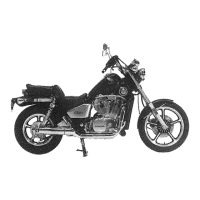
Honda 1984 Shadow VT700C Specifications

General IconGeneral
IgnitionCDI
StartingElectric
Transmission6-speed
Final DriveShaft
Front SuspensionTelescopic fork
Front BrakeSingle disc
Rear BrakeDrum
Front Tire100/90-19
Rear Tire140/90-15
Rear SuspensionDual shocks
Fuel Capacity13 liters
Fuel System2x Keihin carburetors

Related product manuals