Crankshaft Angle (Ns) Sensor
----------------
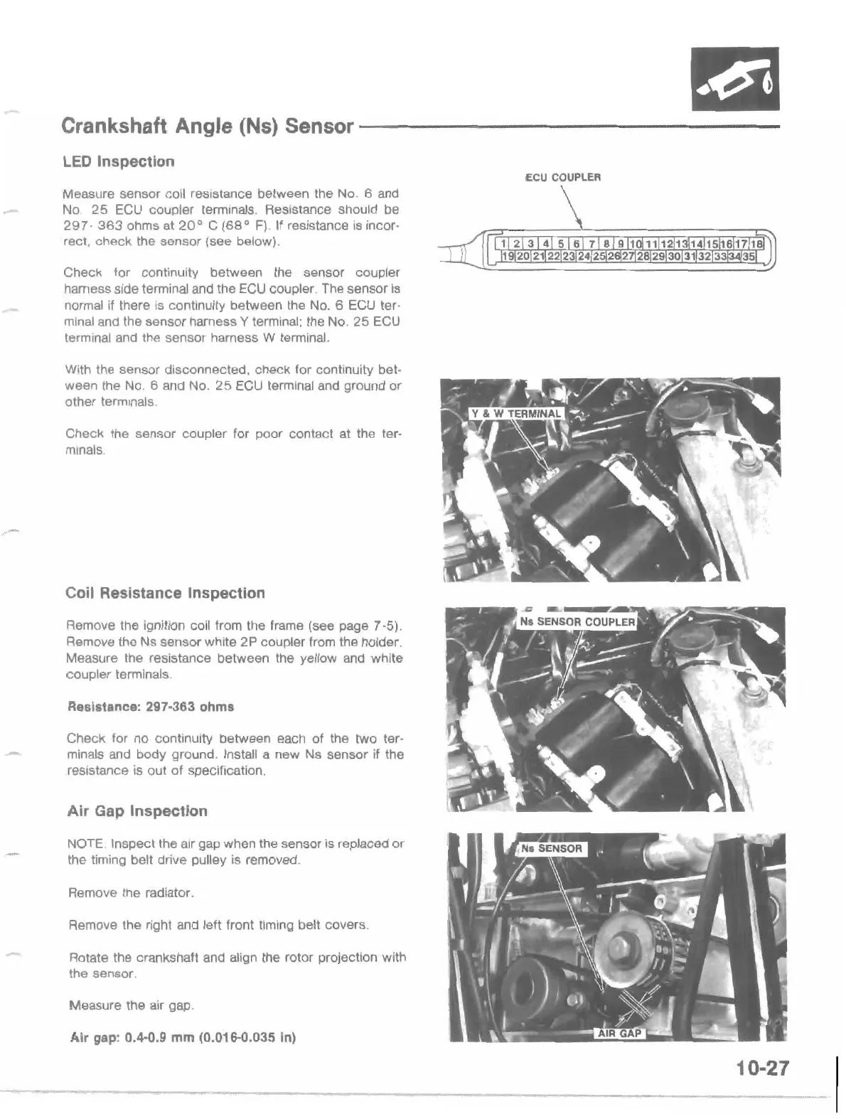
LED
Inspection
ECU COUPLER
Measure sensor coil resistance between the
NO.6
and
No
25
ECU
coupler terminals. Resistance should be
297·
363
ohms at
20
0
C
(68
0
F}. If resistance
is
incor-
rect,
check
the sensor (see below).
Check for continuity between the sensor coupler
harness side terminal and the
ECU
coupler. The sensor
is
normal if there
is
continuity between the
NO.6
ECU ter-
minal and the sensor harness Y terminal; the No.
25
ECU
terminal
and
the sensor harness W terminal.
With the sensor disconnected. check for continuity bet·
ween the
NO.6
and No.
25
ECU terminal and ground or
other terminals
Check the sensor coupler for poor contact at the ter-
minals.
Coil Resistance Inspection
Remove the ignition coil from the frame (see page 7-5).
Remove the Ns sensor white
2P
coupler from the holder.
Measure the resistance between the yellow and white
coupler terminals.
Resistance: 297·363
ohms
Check for no continuity between each
of
the two ter·
minals and body ground. Install a new Ns sensor if the
resistance
is
out of specification.
Air
Gap Inspection
NOTE Inspect the air gap when the sensor is replaced
or
the timing belt drive pulley is removed.
Remove the radiator.
Remove the right and left front timing belt covers.
Rotate the crankshaft and align the rotor projection with
the sensor.
Measure the air gap.
Air
gap:
O.~O.9
mm
(0.016-0.035 In)
10-27

 Loading...