The cam sooft
is
driven
by
chain through the timing gear
reductioned
1/2. As the
cylinder
head
is
mode
of
light
alloy,
not
only
it
is
light
but
cooling
efficiency
is
ex-
cellent
as
heat
conductivity
is
good,
and
shope
of
combustion
chamber
is
ideal semi-
spherical
one
to
get
efficient
combustion
of
mixture and
also
to
attain
larger
com-
pression ratio.
As the
cylinder
is
machined with high rate
of
precision
cooling
efficiency
and
lubrication
are
favorabl
e,
accordingly
wearing
effect
is
v
er
y small. Single
row
W
type
Needle
Bearing
is
used
at
the
big
end
of
the connecting
rod
to
get ample
loading
capacity
at
the
bearing.
On
the other hand single r
aw
Boll Bearings are used
on
the crankshaft,
where
W t
ype
middle parts
at
2 stations single
raw
the needle bearing are used
to
get
larg
er
loading
capacity.
As crankshaft has on
impo
rtant
function
to
convert
reciprocating
motion
to
rotation,
inertia
force
due
to
reciprocating
motion
of
piston and
connecting
rod
should be reduced
. h t t
th
01
t'
on
The crankshaft
can
rotate
smooth
by
putting
balance
welg t a ge smoo rev u I .
running
as
it
is
balanced
by
dynamic
balance
on the balancing machine
after
complete
maching.
To
reduce
vibration
at high speed
revolution
and
to
get
stability
at
high speed running
the right and left cronk arm angle
of
Model
CB72
,
CB77-1
crankshaft
is
set
180
degree.
IFor M
ode
l
C72,
C77
type
angle
is
360
degreel
CD
®
®
®
96
Fig. 2 ·2. Type
·1
crankshaft
CD
Piston
®
Ro
l
te
r
bearing
® Connecting rod
o R·crankshaft
® 6205 Z speciat ball bearing
® Com chaim sprocket
CD
l.
crank shaft
®
Oil
pump drive
gear
Fig. 2
-3.
Type·lt crankshaft
,
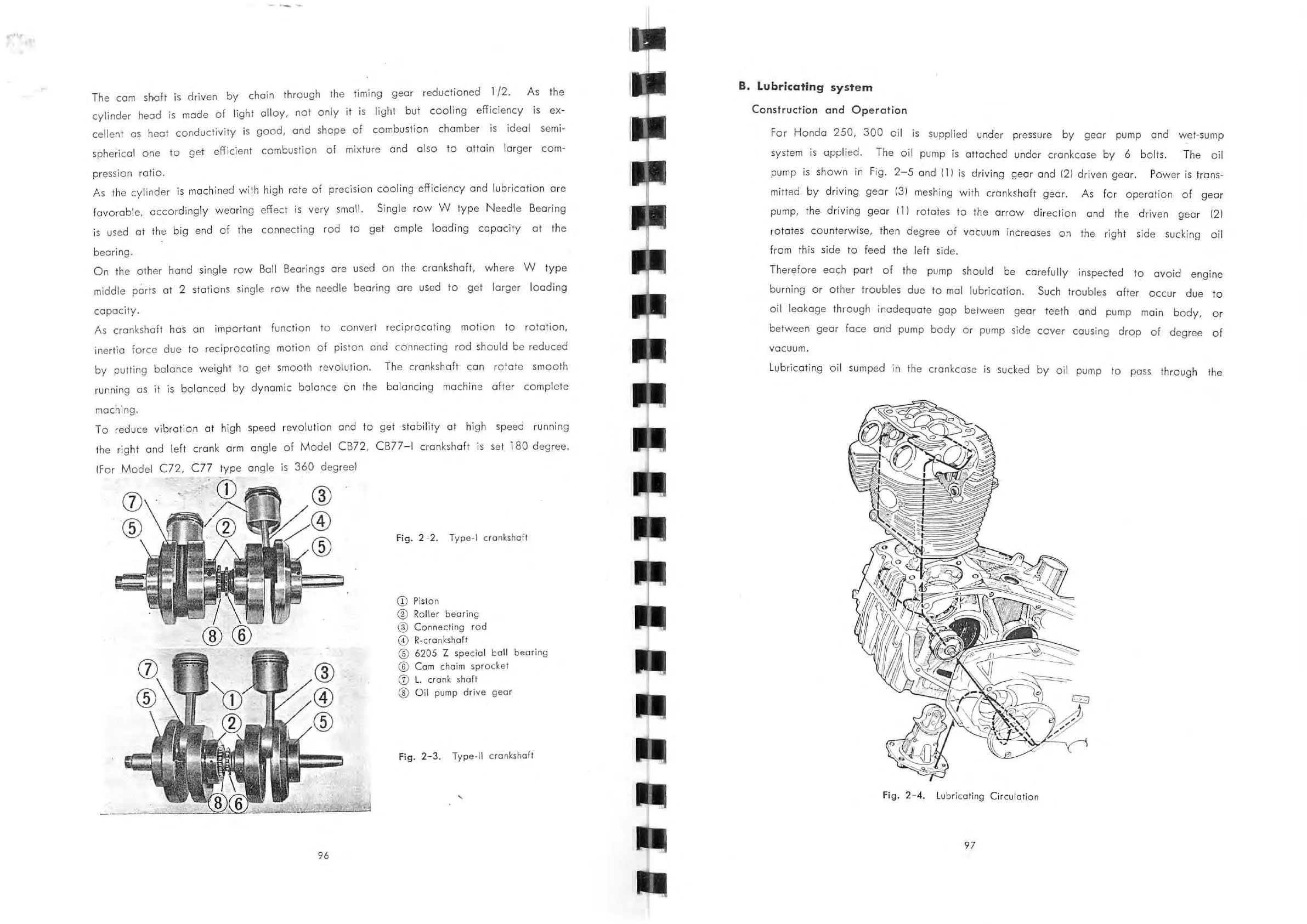
B. LUbricating
system
Construction
and
Op
e
ration
For
Hondo
250,
300
oil
is
supplied under pressure
by
gear pump and wet-sump
system
is
applied.
The
oil
pump
is
attached under crankcase
by
6 bolts. The
oil
pump
is
shown
in Fig.
2-5
and
II
I
is
driving
gear
and
121
driven gear. Power
is
trans-
mitted
by
driving
gear
131
meshing with crankshaft gear. As
for
operation
of
ge
ar
pump, the·
driving
gear
1 I I rotates
to
the arrOw
direction
and the driven
gear
121
rotates
counte
rwise, then degree
of
vacuum increases on the right side sucking
oi
l
from this side
to
feed the left side.
Therefore each
port
of
the pump should be
carefully
inspected
to
avoid
engine
burning
or
other
troubles due
to
mol l
ubrication.
Such troubles
after
OCCur
due
to
oil
leakage through
inadequate
gop
between gear teeth and pump main
body,
or
between
gear
face
and
pump
body
Or pump side
cover
causing
drop
of
degree
of
vacuum .
L
ubricating
oil
sumped in the crankcase
is
sucked
by
oil
pump
to
pass through the
Fi
g. 2- 4. L
ub
ricating Circulation
97
 Loading...