Do you have a question about the Honda C77 and is the answer not in the manual?
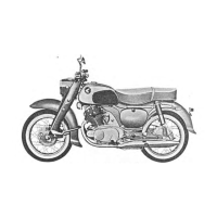
Manual for Honda models C72/C77, CS72/CS77, CB72/CB77.
Introduction to the shop manual, its purpose, and scope.
Technical specifications and dimensions for maintenance.
Procedures for engine disassembly and assembly for C72/C77 models.
Procedures for engine disassembly and assembly for CB72/CB77 models.
Procedures for frame disassembly and assembly for CB72/CB77 models.
Detailed procedures for cylinder disassembly and assembly.
Procedures for left cover disassembly and assembly.
Procedures for right cover disassembly and assembly.
Procedures for transmission (crank) disassembly and assembly.
Procedures for cylinder head disassembly and assembly.
Procedures for oil pump disassembly and assembly.
Procedures for rear fork disassembly and assembly.
Procedures for front fork disassembly and assembly.
Procedures for cylinder disassembly and assembly for CB72/77 models.
Procedures for rear fork disassembly and assembly for CB72/77 models.
Procedures for front fork disassembly and assembly for CB72/77 models.
Procedures for front fork assembly and front fender.
Comparison of constructional features between Honda 250/300 models.
Information on the ignition system components: coil, magneto, contact breaker, spark plug.
Details on electric power generation system (AC Generator, DC Dynamo).
Information on the rectifier component (Selenium rectifier).
Details on the battery system and its maintenance.
Explanation of terms like Maintenance Items, Standard Value, Repairing Limit, Remarks, and Unit in Chart.
Defines standard size and size-limit after assembly or adjustment.
Defines unusable wear limit of parts requiring correction or replacement.
General performance data including compression pressure, fuel consumption, and max speed.
Details regarding the engine and its components.
Specifications for cylinder, cylinder head, and related components.
Specifications for the handle, throttle, and levers.
Specifications for the front suspension components.
Details on the condenser component.
Procedure for head cover disassembly and assembly.
Procedure for cam chain tensioner adjustment.
Procedure for sparking plug installation.
Procedure for left cover disassembly and assembly.
Procedure for oil filter disassembly and assembly.
Procedure for starting motor cable disassembly.
Procedure for starting motor and side cover disassembly.
Procedure for upper crank case disassembly.
Procedure for under crank case disassembly.
Procedure for cylinder head cap removal.
Procedure for contact breaker disassembly.
Procedure for cylinder head side cover disassembly.
Procedure for oil pump strainer disassembly.
Procedure for oil pump packing disassembly.
Procedure for snap ring removal.
Procedure for rear brake wire disassembly.
Procedure for rear brake stopper arm disassembly.
Procedure for head light disassembly.
Procedure for wiring disassembly.
Procedure for carburettor disassembly.
Procedure for cylinder head cover disassembly.
Procedure for cotter pin removal.
Procedure for rear wheel axle disassembly.
Procedure for brake wire disassembly.
Procedure for front brake stopper arm disassembly.
| Engine Configuration | Parallel Twin |
|---|---|
| Displacement | 305 cc |
| Compression Ratio | 8.5:1 |
| Transmission | 4-speed |
| Fuel System | Carburetor |
| Front Suspension | Telescopic Fork |
| Seat Height | 780 mm |
| Weight | 150 kg |
| Dry Weight | 140 kg |
| Final Drive | Chain |
| Frame Type | Steel |
| Fuel Capacity | 12 liters |
| Bore x Stroke | 60 mm x 54 mm |
| Rear Suspension | Swingarm |
| Brakes | Drum |