Do you have a question about the Honda CBR900 and is the answer not in the manual?
Procedures for using genuine parts and tools, and general maintenance practices.
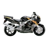
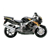
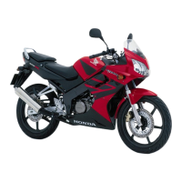
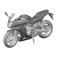
Details on identifying the motorcycle model and its components.
Technical data and specifications for the motorcycle.
Specified torque settings for various fasteners.
Recommended tools for service and maintenance.
Locations and types of lubricants and sealants required.
Diagrams showing the routing of cables and wiring harnesses.
Information on emission control systems and regulations.
Details about emission control labels specific to the USA market.
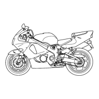
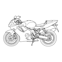
Identification of major body panel locations on the motorcycle.
General service notes and precautions for body panels and exhaust system.
Specified torque settings for frame, body panels, and exhaust system fasteners.
Common problems and solutions for frame, body panels, and exhaust system.
Procedures for removing and installing the seat.
Procedures for removing and installing the pillion seat and rear cowl.
Procedures for removing and installing the middle and lower cowls.
Procedures for removing and installing the upper cowl.
Procedures for removing and installing the inner middle cowl.
Procedures for removing and installing the inner panel.
Procedures for removing and installing the front fender.
Procedures for removing and installing the rear fender.
Procedures for removing and installing the seat rail.
Procedures for removing and installing the muffler and exhaust pipe.
General service information and warnings for maintenance.
Recommended maintenance intervals and tasks.
Technical specifications relevant to maintenance tasks.
Specified torque settings for maintenance-related components.
Tools required for specific maintenance procedures.
Common maintenance issues and their solutions.
Procedures for inspecting and maintaining the fuel line.
Procedures for checking and adjusting throttle operation.
Procedures for inspecting and replacing the air cleaner element.
Procedures for inspecting and replacing spark plugs.
Procedures for inspecting and adjusting valve clearance.
Procedures for checking and changing engine oil and oil filter.
Procedures for checking and adjusting engine idle speed.
Procedures for checking and replacing radiator coolant.
General inspection and maintenance of the cooling system.
Information on the secondary air supply system.
Maintenance of the evaporative emission control system for California models.
Procedures for inspecting, cleaning, and lubricating the drive chain.
Procedures for checking and replacing brake fluid.
General inspection of the brake system.
Procedures for adjusting brake lever position.
Procedures for adjusting brake pedal height.
Procedures for adjusting the brake light switch.
Procedures for adjusting headlight aim.
Procedures for inspecting and adjusting the clutch system.
Procedures for inspecting and checking the side stand.
Procedures for inspecting and adjusting front and rear suspension.
Checking tightness of chassis nuts and bolts.
Procedures for checking tire pressure and condition.
Procedures for checking steering head bearings.
General service information and precautions for the lubrication system.
Technical specifications related to the lubrication system.
Specified torque settings for lubrication system components.
Tools required for lubrication system service.
Common problems and solutions for the lubrication system.
Procedures for inspecting engine oil pressure.
Procedures for removing and inspecting the oil strainer and pressure relief valve.
Procedures for removing, disassembling, and inspecting the oil pump.
Procedures for removing and installing the oil cooler.
General service information and warnings for the fuel system.
Common problems and solutions for the fuel system.
Identification of fuel system components on the motorcycle.
Wiring diagrams for the fuel injection system.
Diagnostic codes indicated by the Malfunction Indicator Lamp (MIL).
Procedure for inspecting peak voltage in the fuel system.
How to connect the test harness for diagnostics.
Layout of test harness terminals for ECM connectors.
Troubleshooting procedure for MAP sensor faults indicated by 1 MIL blink.
Troubleshooting procedure for MAP sensor faults indicated by 2 MIL blinks.
Troubleshooting procedure for ECT sensor faults indicated by 7 MIL blinks.
Troubleshooting procedure for TP sensor faults indicated by 8 MIL blinks.
Troubleshooting procedure for IAT sensor faults indicated by 9 MIL blinks.
Troubleshooting procedure for Vehicle Speed Sensor faults indicated by 11 MIL blinks.
Troubleshooting procedure for No. 1 Injector faults indicated by 12 MIL blinks.
Troubleshooting procedure for No. 2 Injector faults indicated by 13 MIL blinks.
Troubleshooting procedure for No. 3 Injector faults indicated by 14 MIL blinks.
Troubleshooting procedure for No. 4 Injector faults indicated by 15 MIL blinks.
Troubleshooting procedure for Cam Pulse Generator faults indicated by 18 MIL blinks.
Troubleshooting procedure for Ignition Pulse Generator faults indicated by 19 MIL blinks.
Troubleshooting for O₂ sensor faults (California) indicated by 21 MIL blinks.
Troubleshooting for O₂ sensor heater faults (California) indicated by 23 MIL blinks.
Troubleshooting for E²-PROM faults indicated by 33 MIL blinks.
Troubleshooting EGCV/Air Intake Valve Servo Motor voltage faults indicated by 34 MIL blinks.
Troubleshooting EGCV/Air Intake Valve Servo Motor faults indicated by 35 MIL blinks.
Procedures for inspecting the fuel line for leaks or damage.
Procedures for inspecting fuel flow rate.
Procedures for inspecting and replacing the fuel pump.
Procedures for replacing the fuel filter.
Procedures for removing and installing the fuel tank.
Procedures for removing and installing the air cleaner housing.
Procedures for removing and installing the throttle body.
Procedures for inspecting and installing injectors.
Procedures for removing and installing the pressure regulator.
Procedures for disassembling and inspecting the fast idle wax unit.
Procedures for disassembling and assembling the starter valve.
Procedures for synchronizing the starter valves.
Procedures for inspecting and removing/installing the MAP sensor.
Procedures for removing and installing the IAT sensor.
Procedures for removing and installing the ECT sensor.
Procedures for removing and installing the cam pulse generator.
Procedures for inspecting and testing the TP sensor.
Procedures for inspecting and installing the bank angle sensor.
Procedures for inspecting the engine stop relay.
Procedures for inspecting the ECM.
Inspecting power and ground lines for the ECM.
Procedures for inspecting the PAIR solenoid valve.
Procedures for removing and inspecting the EVAP purge control valve.
Procedures for removing and inspecting the O₂ sensor.
Procedures for inspecting the EGCV and air intake valve.
Procedures for disassembling and assembling the variable air intake valve.
General service information and warnings for the cooling system.
Technical specifications for the cooling system.
Specified torque settings for cooling system components.
Common problems and solutions for the cooling system.
Procedure for testing coolant gravity using a hydrometer.
Procedures for inspecting the radiator cap and system pressure.
Procedures for replacing engine coolant and bleeding the system.
Procedures for removing, inspecting, and installing the thermostat.
Procedures for removing and installing the radiator.
Procedures for inspecting, removing, and installing the water pump.
Procedures for removing and installing the radiator reserve tank.
General service information and precautions for engine removal/installation.
Key specifications and data for engine service.
Specified torque settings for engine mounting and related components.
Procedures for removing the lower bracket assembly.
| Compression Ratio | 11.0:1 |
|---|---|
| Transmission | 6-speed |
| Ignition | Computer-controlled digital |
| Front Suspension | Telescopic fork |
| Rear Suspension | Pro-Link single shock |
| Front Brakes | Dual hydraulic disc |
| Rear Brakes | Single hydraulic disc |
| Dry Weight | 185 kg |
| Seat Height | 810 mm |
| Fuel Capacity | 18 liters |
| Engine | Liquid-cooled, inline four-cylinder |