EasyManua.ls Logo

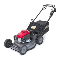
Honda HRD536 User Manual

Honda HRD536
119 pages
To Next Page IconTo Next Page
Page #1 background imageLoading...
Page #1 background image
INDEX
1. SPECIFICATIONS ..........................................3
1.1 General specifications ....................................3
1.2 Dimensional drawings ....................................9
1.3 Wiring diagrams ........................................10
2. SERVICE INFORMATION....................................11
2.1 General safety .........................................11
2.2 Service rules ..........................................11
2.3 Serial number location ...................................11
2.4 Maintenance standards ..................................12
2.5 Torque values .........................................13
2.6 Special tools...........................................14
2.7 Troubleshooting ........................................15
2.8 Maintenance schedule ...................................19
3. MAINTENANCE ...........................................20
3.1 Oil...................................................20
3.2 Spark plug ............................................22
3.3 Air cleaner ............................................23
3.4 Throttle cable ..........................................24
3.5 Drive clutch cable (except H type) ..........................25
3.6 Rotostop cable .........................................25
3.7 Shift cable (except Q type) ................................27
3.8 Valve clearance ........................................28
3.9 carburetor.............................................29
3.10 Governor .............................................29
3.11 Fuel filter .............................................30
3.12 Blade ................................................30
3.13 Spark arrester (optional part) ..............................31
4. BLADE / ROTOSTOP .......................................32
4.1 Principe de fonctionnement du rotostop .....................32
4.2 Blade brake clutch ......................................33
4.3 Inspection du rotostop ...................................36
4.4 Driven disc, drive disc ...................................37
4.5 Ball control assembly ....................................39
4.6 Blade sharpening .......................................40
5. ENGINE REMOVAL / INSTALLATION..........................41
5.1 Engine removal ........................................41
5.2 Engine installation ......................................43
6. AIR CLEANER / MUFFLER ..................................45
6.1 Air cleaner ............................................45
6.2 Muffler ...............................................46
7. RECOIL STARTER / FUEL TANK .............................47
7.1 Fuel tank .............................................47
7.2 Recoil starter ..........................................49
8. IGNITION COIL / CONTROL ARM / carburetor ..................52
8.1 Ignition coil / Engine stop switch ...........................52
8.2 Control assembly .......................................55
8.3 carburetor.............................................59
9. FLYWHEEL / STARTER MOTOR..............................61
9.1 Flywheel..............................................61
9.2 Starter motor / Charging coil ..............................62
10. CYLINDER HEAD / VALVES .................................66
10.1 Removal / Installation....................................66
10.2 Disassembly / Reassembly ...............................67
10.3 Inspection.............................................68
10.4 Valve guide replacement .................................69
10.5 Valve seat reconditioning.................................70
11. OIL PAN / DRIVE SHAFT / GOVERNOR ........................72
11.1 Oil pan ...............................................72
11.2 Drive shaft / Governor ...................................74
12. CRANKSHAFT / PISTON / CYLINDER .........................75
12.1 Disassembly / Reassembly ...............................75
12.2 Inspection.............................................78
13. FRONT WHEEL / REAR WHEEL ..............................82
13.1 Front wheel ...........................................82
13.2 Rear wheel............................................84
14. REAR DRIVE SYSTEM......................................86
14.1 Transmission/Hydrostatic transmission (HRD535/K1/K2
HRD536/K1/K2) ........................................86
14.2 Transmission/Hydrostatic transmission (HRD535K1 TME) .......91
14.3 Transmission/Hydrostatic transmission (HRA536) .............93
14.4 Rear roller ...........................................101
15. HANDLE / CONTROL LEVERS ..............................105
15.1 Upper handle .........................................105
15.2 Lower handle .........................................108
15.3 Control lever..........................................109
15.4 Wire / Harness routing ..................................111
16. CONTROL BOX ..........................................114
16.1 Control box...........................................114
16.2 Combination switch ....................................115
16.3 Battery ..............................................115
16.4 Regulator / Rectifier ....................................117
17. DISCHARGE GUARD / GRASS BAG .........................118
17.1 Discharge guard.......................................118
17.2 Grass bag ...........................................119
SAFETY INSTRUCTIONS
Pay attention to these symbols and their meaning:
Indicates a high risk of severe personal injury or death if instructions are not
followed.
CAUTION:
Indicates a possibility of personal injury or equipment damage if instructions are not
followed.
-2-
HRA536 - HRD535 - HRD536
Table of Contents

Other manuals for Honda HRD536

Questions and Answers:

Honda HRD536 Specifications

General IconGeneral
EngineHonda GCV160
Engine Displacement160 cc
Engine Type4-stroke
Engine Displacement (Alternative)0.16 litres
Cutting Height AdjustmentSingle lever

Summary

2.7 Troubleshooting

a. General symptom and possible causes

Diagnoses engine starting and power issues by listing symptoms and their potential causes and checks.

b. Starter motor / Charging system

Troubleshoots starter motor and charging system failures, guiding through checks for faulty components.

c. Hard starting

Step-by-step guide to diagnose and resolve hard starting issues, covering fuel, ignition, and compression checks.

d. Ignition system

Troubleshoots ignition system problems like no spark or poor spark, guiding through plug, cap, and coil checks.

3. MAINTENANCE

3.1 Oil

Details engine oil checking, changing procedures, recommended oil types, and capacities for different models.

3.1 Oil

3.2 Spark plug

3.3 Air cleaner

3.8 Valve clearance

3.9 carburetor

a. Idle speed adjustment

Instructions for adjusting the engine idle speed using the throttle stop screw to meet standard specifications.

b. Pilot screw adjustment

Guidance on adjusting the pilot screw for optimal idle speed, with precautions to avoid seat damage.

3.12 Blade

4. BLADE / ROTOSTOP

4.2 Blade brake clutch

c. Models HRD535K1: 8106640 ~, HRD536K1: 8107479 ~ HRD535K2 - HRD536K2

Instructions for disassembling and reassembling the Rotostop mechanism for specific HRD models, with torque values and checks.

4.4 Driven disc, drive disc

4.5 Ball control assembly (HRD535 Q /K1 Q /K2 Q - HRA536)

4.6 Blade sharpening

5. ENGINE REMOVAL / INSTALLATION

5.1 Engine removal

Detailed steps for safely removing the engine from the mower, including draining fluids and disconnecting cables and components.

5.2 Engine installation

6. AIR CLEANER / MUFFLER

7. RECOIL STARTER / FUEL TANK

7.2 Recoil starter

8. IGNITION COIL / CONTROL ARM / CARBURETOR

8.1 Ignition coil / Engine stop switch

Procedures for removing, installing, and inspecting the ignition coil and engine stop switch for different models.

8.1 Ignition coil / Engine stop switch

8.2 Control assembly

8.3 Carburetor

9. FLYWHEEL / STARTER MOTOR

9.1 Flywheel

Steps for removing and installing the flywheel, including special tool usage and magnet handling precautions.

9.2 Starter motor / Charging coil

10. CYLINDER HEAD / VALVES

10.1 Removal / Installation

Steps for removing and installing the cylinder head assembly, including gasket replacement and torque specifications.

10.2 Disassembly / Reassembly

10.4 Valve guide replacement

VALVE GUIDE REAMING

10.5 Valve seat reconditioning

11. OIL PAN / DRIVE SHAFT / GOVERNOR

11.1 Oil pan

11.2 Drive shaft / Governor

12. CRANKSHAFT / PISTON / CYLINDER

12.1 Disassembly / Reassembly

Detailed guide for disassembling and reassembling the crankshaft, piston, and cylinder, including bearing and seal replacement.

12.1 Disassembly / Reassembly

12.2 Inspection

13. FRONT WHEEL / REAR WHEEL

13.1 Front wheel

13.2 Rear wheel

14. REAR DRIVE SYSTEM

14.1 Transmission / Hydrostatic transmission (HRD535/K1/K2 except TME - HRD536/K1/K2)

Steps for removing the transmission assembly, including draining fluids and disconnecting cables and belts.

14.1 Transmission / Hydrostatic transmission (HRD535/K1/K2 except TME - HRD536/K1/K2)

b. Disassembly / Reassembly

Procedures for disassembling and reassembling the transmission assembly for S and H types, including pulley and spring installations.

c. Transmission installation

Steps for installing the transmission assembly, including cable connections, belt installation, and lever adjustments.

14.2 Transmission / Hydrostatic transmission (HRD535K1/K2 TME)

a. Removal

Steps for removing the transmission assembly on HRD535K1/K2 TME models, including belt guard and cable disconnections.

b. Reassembly

Instructions for reassembling the transmission, including pulley centering and V-belt installation with tensioning.

14.3 Transmission / Hydrostatic transmission (HRA536)

a. Removal / Installation

Procedure for removing and installing the hydrostatic transmission on HRA536 models, including cable and shaft connections.

b. Oil pump disassembly / Reassembly

Detailed steps for disassembling and reassembling the oil pump, including component identification and lubrication.

c. Hydraulic motor disassembly / Reassembly

Steps for disassembling and reassembling the hydraulic motor, including bearing installation and component alignment.

TRANSMISSION CASE

HYDROSTATIC TRANSMISSION AIR BLEEDING

14.3 Rear roller

c. Transmission disassembly / Reassembly

15. HANDLE / CONTROL LEVERS

15.1 Upper handle

Steps for disassembling and reassembling the upper handle assembly, including levers, cables, and springs.

15.1 Upper handle

15.2 Lower handle

a. Disassembly / Reassembly

Procedure for disassembling and reassembling the lower handle assembly for HRD and HRA models, including supports and screws.

15.3 Control lever

a. Disassembly / Reassembly

Steps for disassembling and reassembling the control lever for S and Q types, including shifter, throttle, and spring components.

15.4 Wire / Harness routing

16. CONTROL BOX

16.1 Control box

Steps for disassembling and reassembling the control box, including panel, switch, battery, and regulator/rectifier.

16.1 Control box

16.3 Battery

16.4 Regulator / Rectifier

Related product manuals