FUEL SYSTEM (PGM-FI)
6-65
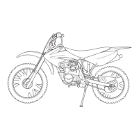
ECM
REMOVAL/INSTALLATION
Remove the rear fender A (page 3-7).
Disconnect the ECM 33P connector.
Remove the ECM from the rubber holder.
Installation is in the reverse order of removal.
Engine Does Not Start (MIL Does Not
Come On)
• Before starting the inspection, check for battery
voltage.
• Before starting the inspection, check for loose or
poor contact on the ECM 33P connector and
recheck.
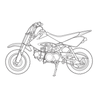
1. ECM Ground Line Inspection
Turn the ignition switch "OFF".
Disconnect the ECM 33P connector.
Check for continuity between the ECM 33P con-
nector of the wire harness side and ground.
Is there continuity?
YES – GO TO STEP 2.
NO – • Open circuit in Green/White wire.
• Open circuit in Green/Black wire.
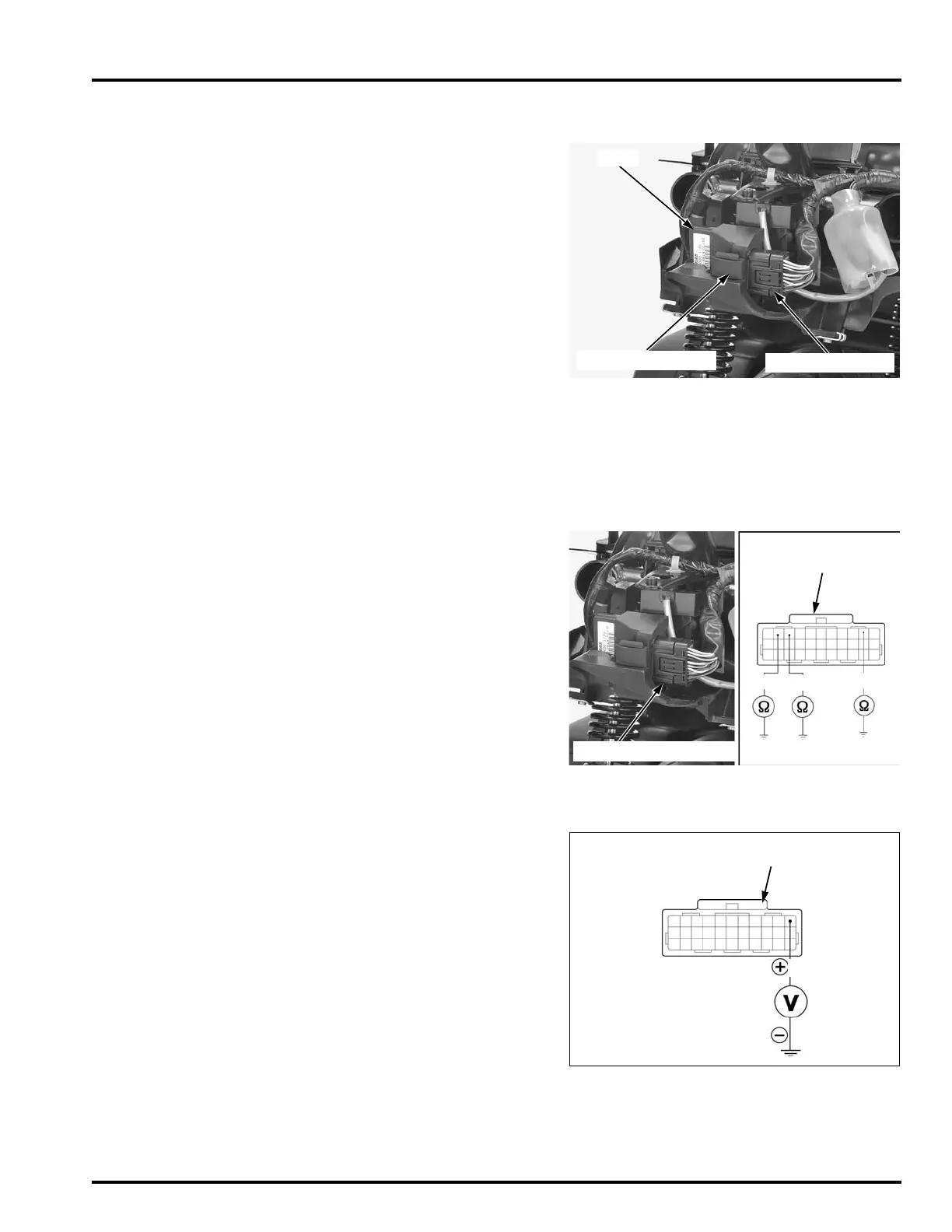
2. ECM Power Line Inspection
Turn the ignition switch "ON".
Measure the voltage between the ECM 33P con-
nector of the wire harness side and ground.
Does the battery voltage exist?
YES – GO TO STEP 3.
NO – GO TO STEP 4.
ECM
33P CONNECTOR
RUBBER HOLDER
CONNECTION: No.9 (Green/White) – Ground
No.10 (Green/White) – Ground
No.2 (Green/Black) – Ground
TOOL:
Test probe 07ZAJ-RDJA110
33P CONNECTOR
(Wire side of female
terminals)
ECM 33P CONNECTOR
G/W
G/W
G/BI
CONNECTION: No.1 (Black/White) (+) – Ground
(–)
TOOL:
Test probe 07ZAJ-RDJA110
33P CONNECTOR
(Wire side of female
terminals)
Bl/W
 Loading...