Do you have a question about the Honda V45 MAGNA-VF750C 1983 and is the answer not in the manual?
| Displacement | 748 cc |
|---|---|
| Compression Ratio | 10.5:1 |
| Transmission | 6-speed |
| Final Drive | Shaft |
| Rear Suspension | Dual shocks, adjustable preload |
| Front Brakes | Dual disc |
| Rear Brakes | Drum |
| Rear Tire | 130/90-16 |
| Bore x Stroke | 70.0 x 48.6 mm |
| Fuel System | 4x Keihin carburetors |
| Front Suspension | Telescopic fork |
Safety precautions for operating and maintaining the motorcycle.
Procedure for checking engine oil level and oil pressure warning.
Steps for changing engine oil and filter.
Steps for removing the oil pump assembly.
Steps for assembling the oil pump components.
Instructions for installing the oil pump and related parts.
Diagram showing all lubrication points on the motorcycle.
Procedure for inspecting and adjusting valve clearance.
Inspection and adjustment of valve clearances for all cylinders.
Procedure for testing cylinder compression.
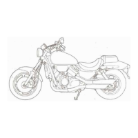
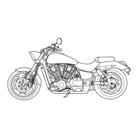
Steps for removing carburetors from the V45 SABRE.
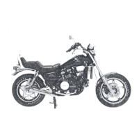
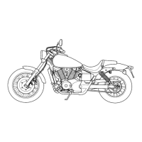
Steps for removing carburetors from the V45 MAGNA.
Steps for removing the vacuum chamber, diaphragm, and piston.
Removing and measuring float level for carburetors.
Removing pilot screw plugs and pilot screws.
Installing and adjusting pilot screws.
Installing carburetors and performing related inspections.
Procedure for adjusting pilot screws for idle drop.
Exploded view and torque values for engine removal.
Exploded view and torque values for engine removal.
Steps for removing the engine, including draining fluids and disconnecting components.
Installing engine mount rubbers, exhaust system, and filling fluids.
Procedure for draining, filling, and bleeding the cooling system.
Steps for removing the thermostat from the cooling system.
Steps for removing the thermostat from the cooling system for V45 MAGNA.
Steps for removing the radiator and cooling fan.
Disassembling the radiator, fan shroud, and fan.
Mechanical seal inspection and water pump removal procedures.
Checking water pump for seal leakage and bearing wear.
Installing new O-rings, water pump shaft, and water pump.
Installing dowel pins, O-ring, water pump cover, hose, crankcase rear cover, and filling coolant.
Common clutch problems and their causes.
Procedure for draining, filling, and bleeding the clutch fluid.
Steps for draining fluid, removing mirror, lever, switch wires, and brake hose.
Steps for disassembling the clutch slave cylinder.
Assembling slave cylinder, installing insulator, connecting hose, and filling fluid reservoir.
Removing starter clutch bolt, assembly, spacer, and primary drive gear.
Installing thrust washer, idle gear shaft, springs, plungers, rollers, and starter clutch cover.
Installing the clutch cover and filling the crankcase with oil.
Steps for removing the gearshift linkage, including draining oil and removing covers.
Installing shift drum cam plate and washer, neutral stopper arm, spring, and arm bolt.
Assembling gearshift spindle, installing washer, stopper arm, collar, spring, and oil pump drive.
Aligning punch marks and installing gearshift pedal assembly and left crankcase cover.
Steps for removing the alternator cover and flywheel.
Removing the seat, cover, alternator coupler, and stator.
Installing woodruff key, flywheel, and alternator cover.
Torque specifications for cylinder head and camshaft components.
Draining coolant and oil, removing radiator, cylinder head covers, and cam chain guide.
Rotating crankshaft, removing rear cylinder cam sprocket bolts, and cleaning sprockets.
Removing camshaft holder dowel pins, intake/exhaust camshafts, and cam sprockets.
Measuring cam lobe diameter and checking for wear.
Loosening hose clamps, removing water pipes, O-rings, oil pipe, and cam chain tensioner.
Removing tensioner slipper, cylinder head bolts, and cylinder heads.
Inspecting cam chain guide, tensioner, slipper, and spring.
Removing rocker arm shaft and rocker arms.
Removing valve spring cotters, retainers, springs, and valves.
Checking spark plug hole and valve areas for cracks, and cylinder head for warpage.
Inspecting rocker arms for wear and measuring I.D.
Measuring rocker arm shaft O.D. and clearance, and inspecting spring.
Inspecting valve stem and measuring valve guide I.D.
Procedure for replacing valve guides, including heating and reaming.
Cleaning valves, inspecting valve face, and refacing valve seats.
Installing valve stem seals, springs, retainers, and cotters.
Cleaning cylinder head, installing dowel pins, gaskets, and cam chain guides.
Installing tensioner base, cylinder head bolts, and checking alignment.
Lubricating camshafts and installing oil pipes and water hoses.
Placing camshafts, indexing sprockets, and installing camshaft holders.
Aligning punch marks, positioning camshafts, and tightening camshaft holder bolts.
Aligning T2.4 mark, positioning camshafts, tightening front cylinder camshaft holders, and installing other cam sprocket bolts.
Tightening tensioner base bolts, installing oil pipes, and releasing tensioner.
Lubricating camshaft, adjusting valve clearance, and installing head cover gaskets.
Removing upper crankcase bolts, mainshaft bearing holder, and lower crankcase bolts.
Removing output gear case, separating crankcase, and removing countershaft bearing.
Installing shift fork, shift drum, transmission, crankshaft, and connecting rods.
Cleaning mating surfaces, applying sealant, and assembling crankcase halves.
Tightening upper crankcase bolts, installing mainshaft bearing holder, and output gear case.
Separating crankcase, checking rod side clearance, and removing bearing caps.
Removing piston pin clips, piston pin, and piston.
Measuring ring-to-groove clearance and inspecting piston.
Measuring ring end gap, piston O.D., cylinder bore, and clearances.
Removing crankshaft and cam chain.
Inspecting bearing inserts and installing bearing caps.
Inspecting bearing inserts, cleaning journals, and installing main bearings.
Selecting replacement bearings based on rod and crankpin codes.
Installing main bearings and crankshaft.
Cleaning pistons, installing rings, and staggering gaps.
Assembling pistons and connecting rods with grease and aligning marks.
Installing rod/piston assemblies, compressing rings, and using rubber hose for crankshaft protection.
Installing and torquing connecting rod caps, and checking rod movement.
Checking gear dogs, holes, teeth, bushings, and mainshaft/countershaft O.D. and clearances.
Separating crankcase, removing dowel pins, and inspecting gear backlash.
Measuring gear I.D., O.D., bushings, and calculating clearances.
Removing dowel pin, O-rings, output gear case, and bearing lock nut.
Replacing countershaft bearings, unstaking lock nut, and removing outer race.
Attaching bearing holder, installing lock nut, and staking it.
Removing oil seal, bearing holder, lock nut, and driven gear.
Replacing bearings and oil seals in the output gear case.
Installing bearing holder, new bearing, shim, and output driven gear.
Attaching bearing holder, installing new inner race lock nut, and staking it.
Applying Prussian Blue to pinion teeth and checking contact pattern.
Evaluating gear tooth contact pattern and replacing shims.
Measuring gear backlash using a dial indicator and comparing measurements.
Measuring clearance between bearing and spacer.
Removing brake disc mounting bolts and discs, side collar, and seals.
Assembling master cylinder, coating parts with fluid, and installing piston.
Troubleshooting ignition system problems like engine not starting or running poorly.
Maintenance schedule for V45 SABRE with service intervals.
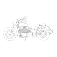
Maintenance schedule for V45 MAGNA with service intervals.
Removing snap ring, clutch lifter plate, bearing, guide, rod, lock nut, and clutch plates.
Installing clutch outer guide, needle bearing, and clutch outer.
Installing clutch center A and washer, clutch inner, one-way clutch, and clutch center B.
Placing transmission in 6th gear, tightening lock nut, installing lifter rod, plate, guide, bearing, and snap ring.
Checking countershaft spacer selection and measuring clearance.
Installing countershaft, gears, washers, and collar.