SERIES-3000 VU52, VU53, VU54; VU442, VU443, VU444; VU842, VU843, VU844 FAN COIL VALVES AND ACTUATORS
95C-10885—01 4
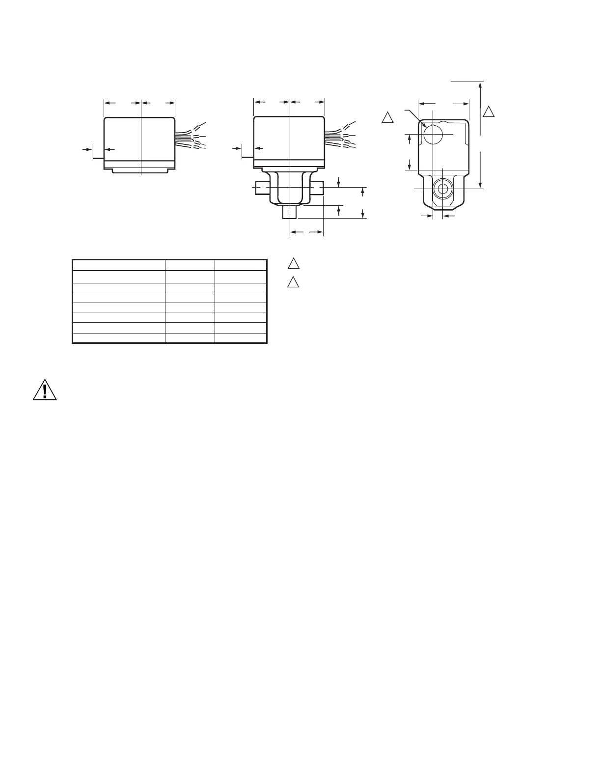
Fig. 1. Mounting Dimensions in in. (mm).
Equipment Damage Hazard
• Foreign particles like sand (quartz), rust, and
metal chips can damage the ball plugs.
• For trouble-free operation of the product, good
installation practice must include initial system
flushing, and chemical water treatment. Clean
the lines upstream of particles larger than 1/16
inch diameter (welding slag, pipe scale, sand
and other suspended particulate). Remove all Y-
strainer filters before flushing.
• Anti-freeze solutions that can be used, with
minimum 50% water dilution, are diethylene
glycol, ethylene glycol, and propylene glycol.
• Do not use boiler additives, solder flux and
wetted materials which are petroleum based or
contain mineral oil, hydrocarbons, or ethylene
glycol acetate. These chemicals can cause O-
rings and ball plug to swell and affect product
performance.
• If installing these valves in an addition to, or
retrofitting an existing building, do not assume
that the fluid in the existing piping meets these
criteria.
• When installing threaded fittings and pipes, if
tape is unavailable use minimum possible
amount of pipe dope. Excessive dope may be
forced into valve seat and interfere with valve
operation when pipe is assembled to body.
IMPORTANT
Hold valve by wrench flats ONLY when tightening
pipe fittings. Do NOT hold the valve body with the
pipe wrench: product damage may result.
1. Proceed with installation once the system specifics
(expansion/contraction of the system and its
medium as well as operating pressures) are within
tolerances.
2. Eliminate air from system.
3. Three-way valves may be installed for mixing or
diverting control.
4. Two-way valves are marked to show flow direction.
IMPORTANT
Flow arrows must point in the direction of the flow
for proper operation and to prevent water hammer.
How to Find Valve Pressure Drop
Valve pressure drop is determined by the formula:
ΔΡ = (gpm/C
v
)
2
x ρ
where ρ is the density of the glycol solution, and typically
ranges between 0.95 and 1.05.
The pressure drop in psi, or feet of water can be
determined from Fig. 2 as follows:
1. Calculate the flow rate to cool and dehumidify.
2. Determine the C
v
rating of the valve.
3. Select the graph corresponding to the C
v
rating of
the valve.
4. Determine the pressure drop across the valve using
the following procedures for calculating pressure
drop:
VU ACTUATOR
3/8
(10)
1-3/4
(44)
1-3/4
(44)
OPENING FOR 1/2 IN. CONDUIT ON OPPOSITE SITE OF
MANUAL LEVER FOR ALL MODELS.
HEIGHT NEEDED TO REMOVE ACTUATOR OR COVER.
VU53 VALVE WITH ACTUATOR
2-3/8
(60)
7/8 DIA.
(22)
1-1/2
(38)
3-3/4
(133)
15/32 (12)
VALVE BODY SIZE
A
B
3/8
(10)
1-3/4
(44)
1-3/4
(44)
7/8 (23)
2-WAY
B
3-WAY
A
A
2 1/8 (54)
(Inverted Flare)
VU52, VU53 AND VU54 VALVE DIMENSIONS WITH ACTUATOR
1
2
1
2
M32076
B
AB
A
1/2 IN. SWEAT 1-5/6 (33) 1-5/16 (33)
3/4 IN. SWEAT 1-3/8 (35) 1-11/16 (43)
1 IN. SWEAT 1-11/16 (43) 1-11/16 (43)
1/2 IN. F-NPT 1-3/8 (35) 1-5/16 (33)
3/4 IN. F-NPT 1-11/16 (43) 1-7/16 (37)
1 IN. F-NPT 1-11/16 (43) 1-7/16 (37)
1/2 IN. INVERTED FLARE 1-3/8 (25) 1-5/16 (33)
 Loading...