SERIES-3000 VU52, VU53, VU54; VU442, VU443, VU444; VU842, VU843, VU844 FAN COIL VALVES AND ACTUATORS
7 95C-10885—01
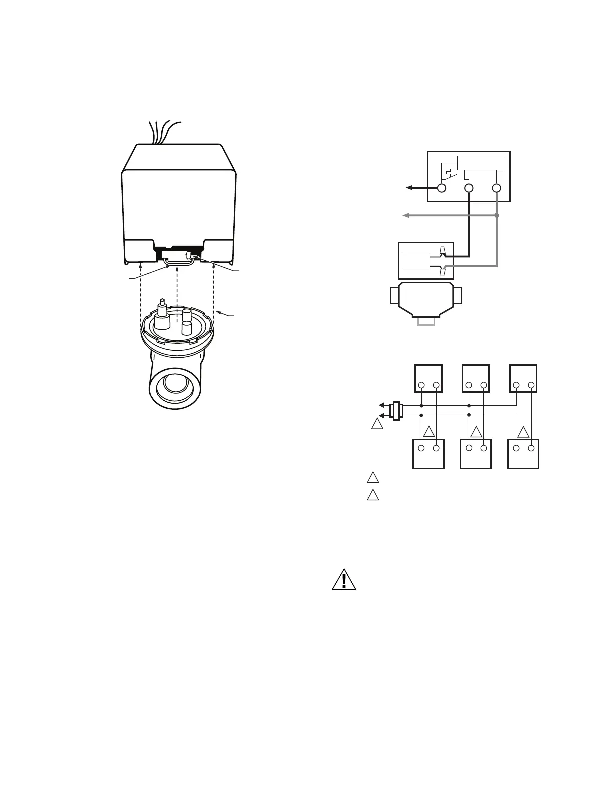
REMOVING ACTUATOR FROM THE
VU-SERIES VALVE BODY ASSEMBLY
(See Fig. 6)
Fig. 6. Removing actuator from valve.
NOTE: It is not necessary to drain the system if the valve
body assembly remains in the pipeline.
1. Switch power supplies OFF. Disconnect electri-
cal leads, carefully noting the position and
color of each lead.
2. Place the manual operating lever in the MAN.
OPEN position. See Fig. 6.
3. Remove actuator by depressing locking button
and lifting straight up.
WIRING
Disconnect the power supply before connecting wiring to
prevent electrical shock or equipment damage. All wiring
must comply with local codes and ordinances. See Fig. 7
and 8 for typical hookups.
To Attach Flexible Conduit
1. Strip cable jacket.
2. Fit conduit strain relief onto cable.
3. Slide strain relief nut over wires.
4. Connect cable and actuator wires.
5. Slide cable wires down through slot in the wiring
hole, so that the strain relief nut is inside the actua-
tor housing.
6. Secure nut onto strain relief.
7. Install actuator cover.
Fig. 7. Typical wiring for VU40-series actuator.
Fig. 8. SPST Thermostat, VU80-series actuator hookup.
OPERATION
ON 24V SYSTEMS, NEVER JUMPER THE VALVE
COIL TERMINALS EVEN TEMPORARILY. THIS
CAN BURN OUT THE HEAT ANTICIPATOR IN THE
THERMOSTAT.
Automatic Operation
On a call for heat or cool by the fan coil thermostat, the
valve motor operates, opening the valve. When the call
ends, the valve closes by integral spring return.
2. DEPRESS
3. LIFT ACTUATOR
1. PLACE OPEN
AUTO
M32081
IMPORTANT
USE MANUAL LEVER TO OPEN ACTUATOR BEFORE
ATTEMPTING TO MOUNT ON VALVE.
OPEN
ELECTRONICS
L1
(HOT)
L2
FAN COIL THERMOSTAT
(TYPICALY T4039, T6069, TB657X)
MOTOR
VU ACTUATOR
L1 L2H / C
M32082
L1
(HOT)
L2
POWER SUPPLY. PROVIDE DISCONNECT MEANS AND
OVERLOAD PROTECTION AS REQUIRED.
CONNECT BLACK LEADWIRE TO THERMOSTAT.
T822 T822 T822
VU VALVE
VU VALVE
VU VALVE
M32083
1
2
1
2
2
2
 Loading...