SERIES-3000 VU52, VU53, VU54; VU442, VU443, VU444; VU842, VU843, VU844 FAN COIL VALVES AND ACTUATORS
95C-10885—01 6
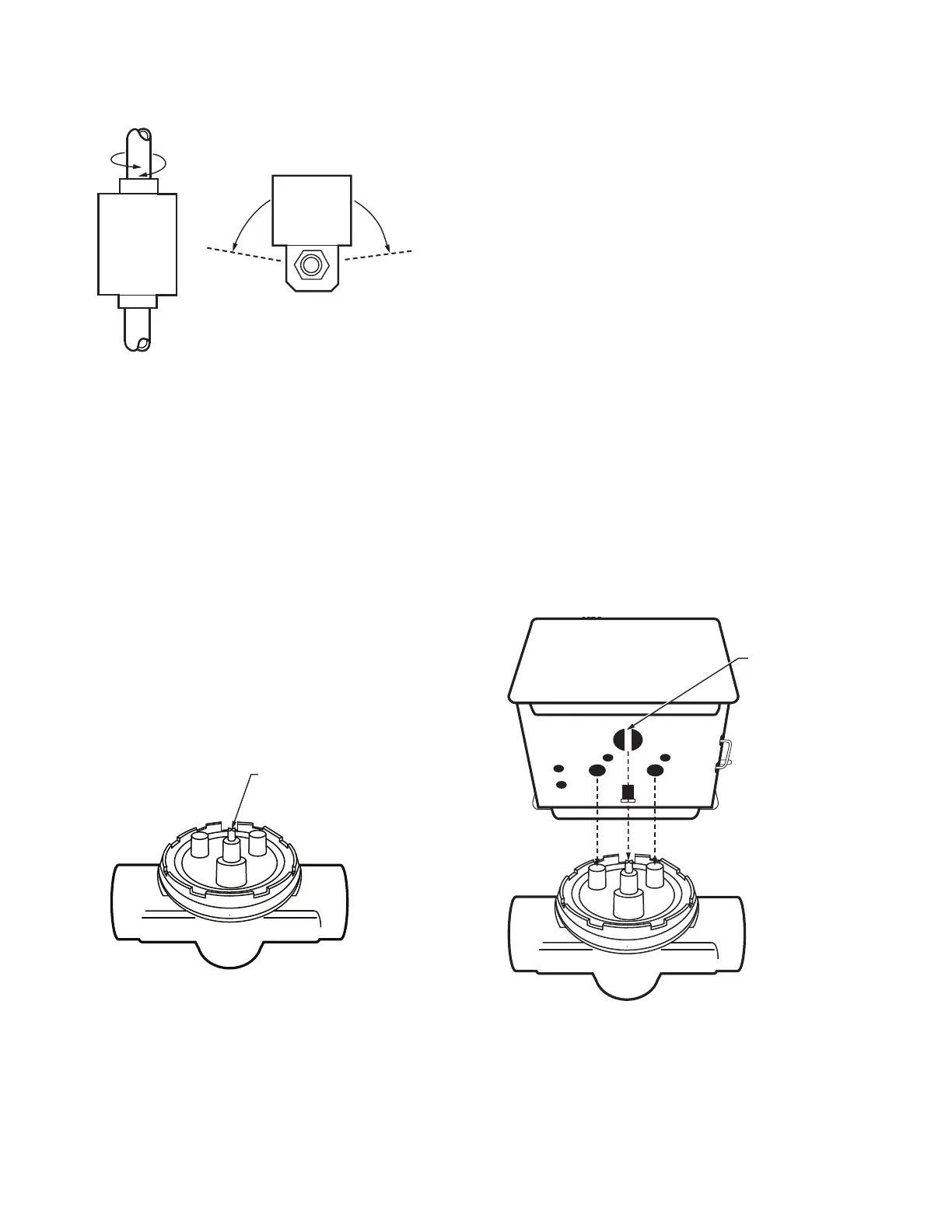
Fig. 3. Mounting positions.
On 3-way valves, the three fittings or ports are labeled on
the bottom of the valve body casting. Port AB is the inlet
port and is open at all times. Port A is closed and port B is
open when the valve is de-energized. Refer to the
equipment manufacturer instructions to determine which
port (A or B) should be connected to the coil bypass. 3-way
valves may be installed as mixing valves after the coil
(recommended) or as diverting valves before the coil.
Sweat Copper Models
1. Use new, properly reamed pipe, free from dents or
corrosion.
2. Place the valve on the pipe. Rotate valve stem so that
the shaft flats point at the notch in the side of the
body (90° to flow directions.) See Fig. 4. This pro-
tects the plug inside the valve by removing it from
the seat.
3. Sweat the joints, keeping the outer surface free from
solder. DO NOT BRAZE sweat bodies without appro-
priate tools because the high temperature can dam-
age main body O-ring and cause leaks.
Fig. 4. Slot position.
To Install & Remove Actuator
INSTALLING ACTUATOR ON VU-SERIES
VALVE BODY ASSEMBLY (See Fig. 5):
1. Orient flats on stem of VU-series valve body at 90° to
water flow (toward notch in side of body). See Fig. 5.
This lifts the ball off seat, prevents damage to the
ball seat while soldering, and makes actuator
attachment easier.
2. Install valve body into pipe.
3. Wiring connections may be made either before or
after actuator installed on valve body.
4. Place manual operating lever on the actuator in the
MAN. OPEN position.
5. Line up motor coupling to slot in shaft of body and
fit the head onto the valve body, ensuring that the
shaft seats correctly. (See Fig. 5.)
6. Snap actuator onto body by pressing down.
7. Make wiring connections. Refer to wiring section for
proper instructions.
Inspect the actuator installation and the valve body to
ensure that all connections and adjustments have been
correctly made. Adjust the thermostat or controller
connected to the valve so that the valve runs through its
cycle. Make sure the valve runs smoothly and positively
from closed to open to closed again.
Fig. 5. Installing new actuator.
M10162A
VERTICAL
PIPING
HORIZONTIAL
PIPING
FLATS ON VALVE STEM
POINTING TO NOTCH ON
SIDE OF VALVE BODY,
AT RIGHT ANGLE TO
LINE OF PIPES
M32078
ACTUATOR
COUPLING
M32080
NOTE: IMPORTANT USE MANUAL LEVER TO OPEN
ACTUATOR BEFORE ATTEMPTING TO MOUNT
ON VALVE.
 Loading...