SERIES-3000 VU52, VU53, VU54; VU442, VU443, VU444; VU842, VU843, VU844 FAN COIL VALVES AND ACTUATORS
© 2021 Resideo Technologies, Inc. All rights reserved.
The Honeywell Home trademark is used under license from Honeywell International, Inc. This product is manufactured by Resideo Technologies, Inc. and its affiliates.
www.resideo.com
Resideo Technologies, Inc.
1985 Douglas Drive North, Golden Valley, MN 55422
1-800-468-1502
95C-10885—01 M.S. Rev. 08-21 | Printed in United States
Manual Operation
The 2-way normally closed and 3-way motorized valve
actuators can be opened manually, without power, by
lifting the manual opening lever over the stop and
pushing slowly and firmly to the MAN. OPEN position. The
stop permits the valve to be locked in the open position.
The valve returns to automatic position when it is
energized.
Normally Closed Models
With the manual opener set to AUTO and the actuator
energized, the A port is opened as shown in the powered
diagrams in Fig. 9 and 10. When the actuator is de-
energized, a spring-return mechanism drives the valve to
the port A closed position as shown in the unpowered
diagrams in Fig. 9 and 10. The valve can also be opened
with no electrical power by moving the manual opening
lever over the stop and pushing slowly and firmly to the
MAN. OPEN position. The stop permits the valve to be
locked in an open position. The valve returns to the
automatic position.
3-way valves may be installed as Normally Closed or
Normally Open by exchanging the orientation of the A and
B ports.
Normally Open 2-way Models
With the manual opener set to AUTO and the actuator
energized, the A port is closed as shown in the powered
diagrams in Fig. 9. When the actuator is de-energized, a
spring-return mechanism drives the valve off the port A as
shown in the “N.O. DE-ENERGIZED” position in Fig. 9 and
10. The manual opener is only used for installing or
removing the actuator from the body.
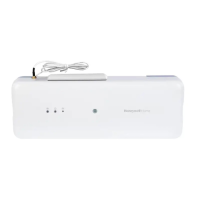
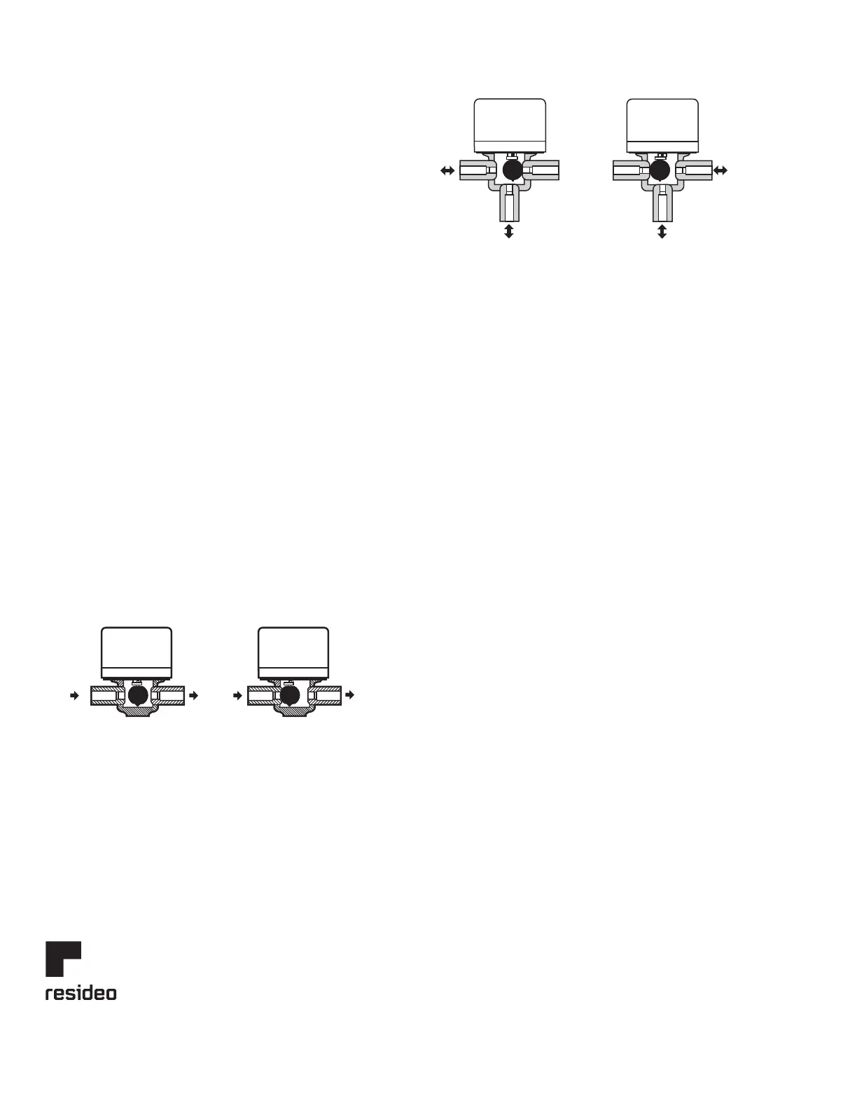
Fig. 9. VU842/442, VU843/443 Actuator operation for
2-way valve.
Fig. 10. VU844/444 Actuator operation for 3-way valve.
CHECKOUT
Set to heating mode
1. Raise the setpoint on the zone thermostat above the
room temperature to initiate a call for heat.
2. Observe all control devices—the valve should open.
3. Lower the setpoint on the zone thermostat below the
room temperature.
4. Observe the control devices. The valve should close.
Set to cooling mode
1. Lower the setpoint on the zone thermostat below the
room temperature to initiate a call for cooling.
2. Observe all control devices—the valve should open.
3. Raise the setpoint on the zone thermostat above the
room temperature.
4. Observe the control devices. The valve should close.
SERVICE
This valve should be serviced by a trained, experienced
service technician.
1. If the valve is leaking, drain the system and check to
see if the O-ring needs replacing.
2. If the gear train is damaged, replace the entire actu-
ator. See the Installation section. If the motor is
burned out, replace the motor.
NOTE: The fan coil valves are designed and tested for
silent operation in properly designed and
installed systems; however, water noises can
occur as a result of excessive water velocity or
piping noises can occur in high temperature
(higher than 212°F (100°C)) systems with insuffi-
cient water pressure. Valves are designed to be
cycled regularly. Product life may be shortened if
energized continuously for extended periods of
time.
B
OUT
OPEN POSITION
N.O. ACTUATOR DE-ENERGIZED
OR N.C. ACTUATOR POWERED
A
IN
B
OUT
CLOSED POSITION
N.O. ACTUATOR POWERED OR
N.C. ACTUATOR DE-ENERGIZED
A
IN
M5951
A
B
OUT/IN
FLOW-THROUGH SERVICE PORT
IN (MIXING)
OUT (DIVERING)
A
B
A
B
OUT/IN
IN (MIXING)
OUT (DIVERING)
A
B
FLOW-THROUGH BYPASS PORT
(UNPOWERED)
Fig. 12A
Fig. 12B
(POWERED)
M32084
 Loading...