6
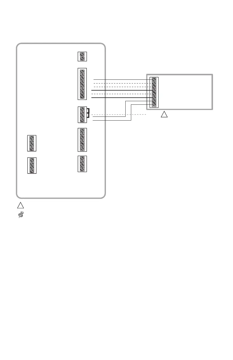
Cableado típico de un sistema convencional con un máximo de calefacción de 3
etapas y de refrigeración de 2 etapas con un transformador.
Guía de cableado del EIM: Sistemas convencionales
R
C
U3
U3
U2
U2
U1
S2
S2
S1
S1
S4
S4
S3
S3
THM04R3000
U1
Y2
G
L
W1
W2
AUX1
W3
AUX2
Y1
RH
RC
R
C
SENSORES
SENSORES SALIDAS DE
CONTACTO EN SECO
24 V CA AL
TERMOSTATO
O/B
CALDERA
G (VENTILADOR)
R (24 V CA VIVO)
W1 (ETAPA 1 DE CALEFACCIÓN)
W2 (ETAPA 2 DE CALEFACCIÓN)
Y1 (ETAPA 1 DE COMPRESIÓN)
Y2 (ETAPA 2 DE COMPRESIÓN)
C (24 V CA COMÚN)
PUENTES
W3 (ETAPA 3 DE CALEFACCIÓN)
11
1
24 V CA
ALIMENTACIÓN
QUITE LOS PUENTES SI UTILIZA TRANSFORMADORES SEPARADOS.
NOTA: CONSULTE LAS SIGUIENTES PÁGINAS PARA OBTENER PAUTAS ADICIONALES SOBRE EL CABLEADO DEL TERMOSTATO
PARA OTROS TIPOS DE SISTEMAS, CABLEADO DE SENSORES, CONTROL IAQ Y OTRAS OPCIONES DE CABLEADO DE CONTACTO
EN SECO.
1
 Loading...