7
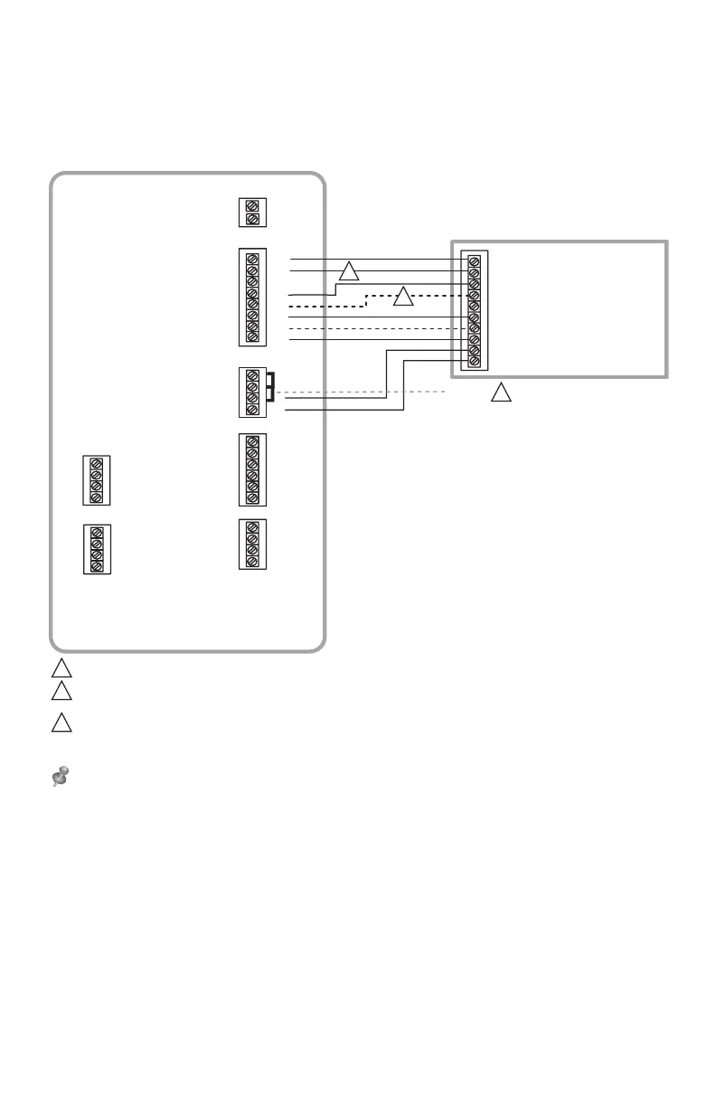
Guía de cableado del EIM: Sistemas de bomba de
calor
Cableado típico de un sistema de bomba de calor con un máximo de calefacción
de cuatro etapas y refrigeración de dos etapas con un transformador.
R
C
S4
S4
S3
S3
AUX1
AUX2
24 V CA AL
TERMOSTATO
U3
U3
U2
U2
U1
S2
S2
S1
S1
THM04R3000
Y2
G
U1
L
W1
W2
W3
Y1
RH
RC
R
C
SENSORES
SENSORES
SALIDAS DE
CONTACTO EN SECO
24 V CA
ALIMENTACIÓN
O/B
BOMBA DE CALOR / CONTROL DE AIRE
G (VENTILADOR)
R (24 V CA VIVO)
AUX 1 (CALEFACCIÓN AUXILIAR)
AUX 2 (ETAPA 2 DE CALEFACCIÓN
AUXILIAR)
Y1 (ETAPA 1 DE COMPRESIÓN)
Y2 (ETAPA 2 DE COMPRESIÓN)
C (24 V CA COMÚN)
PUENTES
11
L (MONITOR DE FALLA DEL SISTEMA)
O (VÁLVULA DE CONVERSIÓN)
1
2
3
QUITE LOS PUENTES SI UTILIZA TRANSFORMADORES SEPARADOS.
LA VÁLVULA DE CONVERSIÓN SE ETIQUETARÁ COMO "O" SI SE ENERGIZA EN REFRIGERACIÓN Y SE ETIQUETARÁ COMO "B" SI SE
ENERGIZA EN CALEFACCIÓN.
LAS ETAPAS DE CALEFACCIÓN AUXILIAR SE ETIQUETAN DE FORMA DIFERENTE EN LOS DISTINTOS CONTROLES DE AIRE DE
BOMBA DE CALOR. LA MAYORÍA DE LAS APLICACIONES DE BOMBAS DE CALOR SOLO CUENTAN CON UNA ETAPA DE
CALEFACCIÓN AUXILIAR.
NOTA: CONSULTE LAS SIGUIENTES PÁGINAS PARA OBTENER PAUTAS ADICIONALES SOBRE EL CABLEADO DEL TERMOSTATO
PARA OTROS TIPOS DE SISTEMAS, CABLEADO DE SENSORES, CONTROL IAQ Y OTRAS OPCIONES DE CABLEADO DE CONTACTO
EN SECO.
1
2
3
 Loading...