6
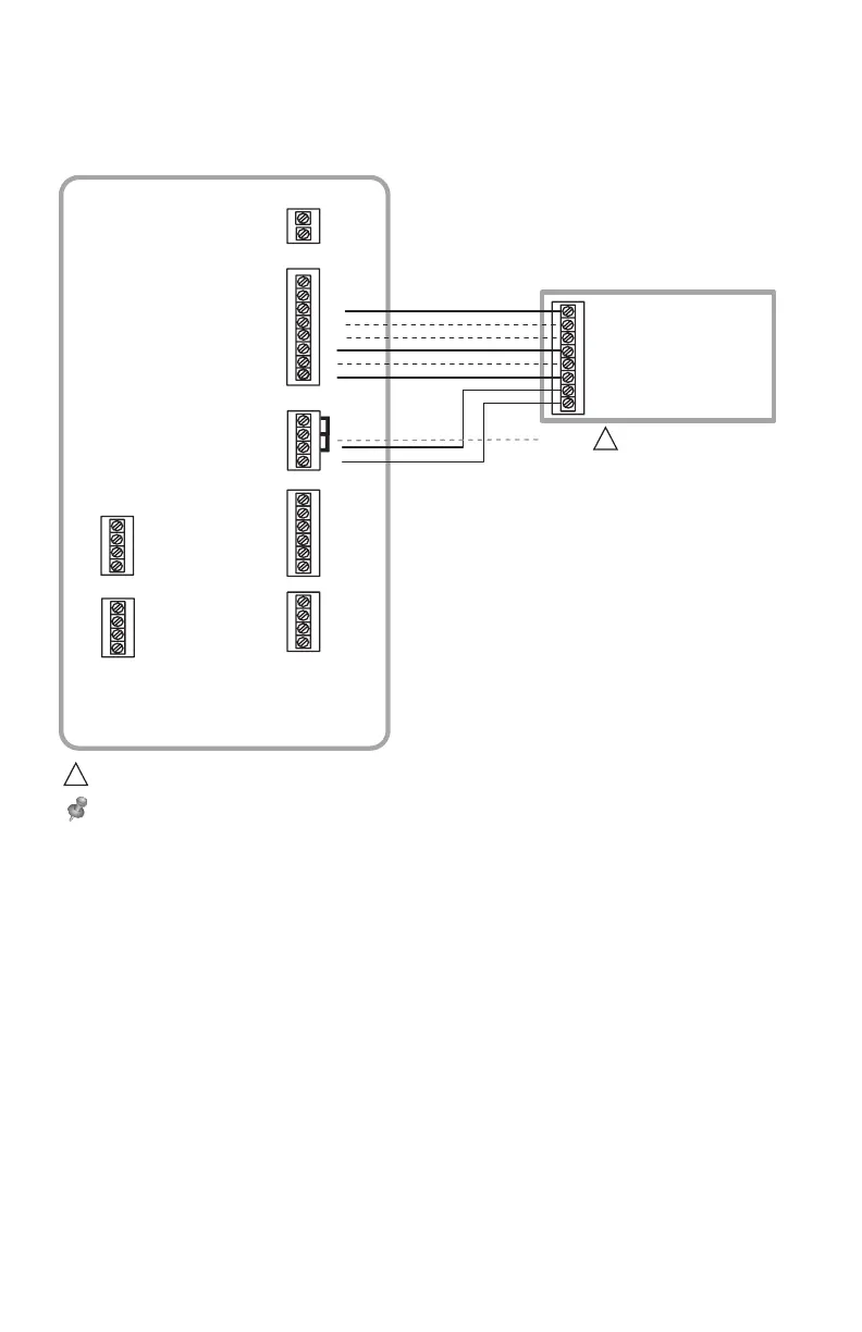
Typical wiring of a conventional system with up to 3 stage heat and 2 stage cool
with one transformer.
EIM wiring guide — conventional systems
R
C
U3
U3
U2
U2
U1
S2
S2
S1
S1
S4
S4
S3
S3
THM04R3000
U1
Y2
G
L
W1
W2
AUX1
W3
AUX2
Y1
RH
RC
R
C
SENSORS
SENSORS DRY CONTACT OUTPUTS
24 VAC TO
THERMOSTAT
O/B
FURNACE
G (FAN)
R (24 VAC HOT)
W1 (HEAT STAG E 1)
W2 (HEAT STAG E 2)
Y1 (COMPRESSOR STAG E 1)
Y2 (COMPRESSOR STAG E 2)
C (24 VAC COMMON)
JUMPERS
W3 (HEAT STAG E 3)
11
1
24 VAC
POWER
REMOVE JUMP ER(S) IF USING SEPARATE TRANSFORMERS.
NOTE: SEE FOLLOWING PAGES FOR ADDI TI ONAL THERMOSTAT WIRING GUIDELINES FOR OTHER SYSTEM TYPES, SENSOR WIRING
IAQ CONTRO L, AND OTHER DRY CONTACT WIRING OPTIONS.
1
 Loading...