Do you have a question about the Honeywell 201-528-24-WH and is the answer not in the manual?
| Voltage | 24V |
|---|---|
| Color | White |
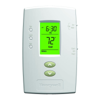
| Compatibility | Single Stage Heating and Cooling Systems |
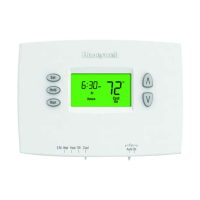
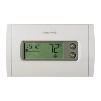
| Display | Digital |
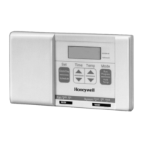
| Type | Non-Programmable |
| Temperature Range | 40°F to 90°F |
| Mounting | Wall |
Precautions for working with high voltages and protection against lightning surges.
Rules for separating wiring to prevent interference and hazards.
Identification of connection terminals for power and signals.
Best practices for thermostat location to ensure accurate readings.
Purpose of Initialization Mode for setup.
Default parameters for comfort control and HVAC operation.
Guide to assigning a unique Room ID to the thermostat.
Steps to select the correct HVAC system type for the thermostat.
Options for configuring fan speed settings.
Enabling contractor mode for construction phase conditioning.
Steps to access the service mode for testing.
Procedure to test the PIR motion sensor functionality.
Procedure to test the door sensor functionality.
Verifying network connection to the INNControl 3 server.
Testing HVAC system response to temperature changes.
How to change the desired room temperature.
Binding devices by setting Room ID, PANID, and RF channel.
Binding devices by mapping input/output functions.
Connecting devices without a user interface, like locks.