4219
GRN
BLK
(–) GROUND
RED
(+) 12VDC
YEL
4321
ZONES
A
B
C
D
F
G H
TB1
TB2
4-PIN CONSOLE PLUG
CONNECTIONS
SAME
AS TB2
1
2
3
4
DATA OUT
TO CONTROL
DATA IN
FROM CONTROL
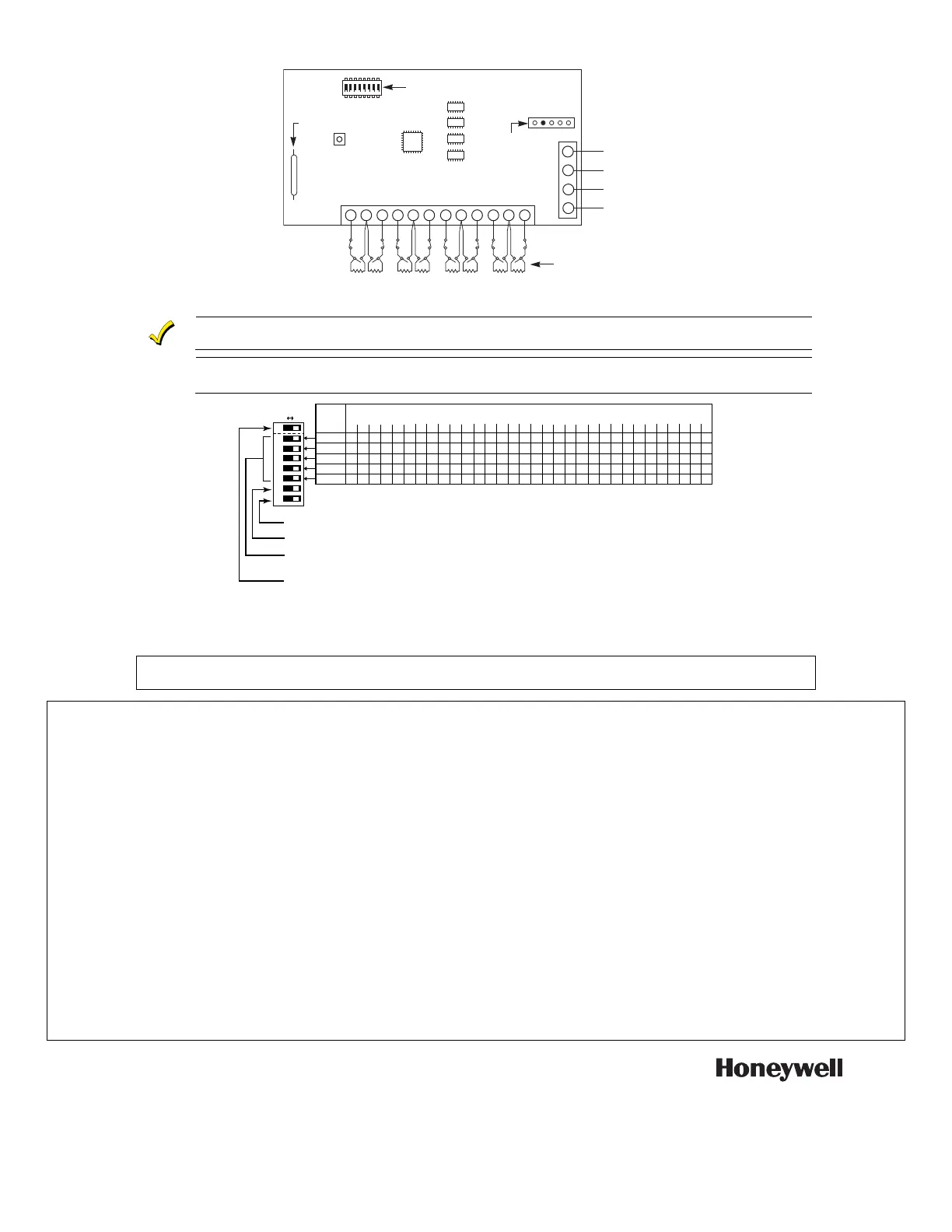
TERMINATE EACH
PROGRAMMED ZONE
WITH 2K OHM
END-OF-LINE RESISTOR
(EACH ZONE'S MAX.
LOOP RESISTANCE:
300 OHMS + EOL)
5
8
11
REED (TAMPER) SWITCH
2
E
1
3
4 6
7
9
10
12
DIP SWITCH FOR SETTING
ADDRESS AND ZONE A RESPONSE
NOTE
FOR CE INSTALLATIONS A
N6361EMI SUPPRESSION
BEAD IS REQUIRED.
4219-SOC-V2
2 3 4 5 61
ON
7 8
Figure 2. Summary of Connections
EOLR value is 2K ohms.
U
L
For UL installations, use 14-22AWG wire, and no more than one wire may be connected per terminal.
42 19 A D DR ES S SE TTI NG S
SWITCH
NUMBER
("—" means "OFF")
0 1 2
3 4 5 6
7
8
9
10
11 12 13
14
15
2
ON
—
ON
—
ON
—
ON
—
ON
—
ON
—
ON
—
ON
—
3
ON
ON
—
—
ON
ON
—
—
ON
ON
—
—
ON ON
—
—
4
ON
ON
ON
ON
—
—
—
—
ON
ON
ON ON
—
—
—
—
5
ON ON
ON
ON ON
ON ON
ON
—
—
—
—
—
— —
—
1 2 3 4 5
➞
OFF ON
DIP SWITCH: (WHITE AREAS DENOTE SWITCH HANDLES)
4219-001-V0
POSITIONS 2-6:
POSITION 1:
DETERMINE ZONE EXPANDER'S ADDRESS. CONSULT CONTROL'S INSTRUCTIONS
FOR ADDRESS USE.
SWITCH SETTING SHOWN SET FOR ADDRESS "0".
DETERMINES ZONE A's RESPONSE TIME:
ON = NORMAL (300MS) RESPONSE, SHOWN (AS SHIPPED).
OFF = FAST (10MS) RESPONSE TO AN OPEN.
6
ON
ON
ON
ON
ON
ON
ON
ON
6 7 8
16 17 18 19 20 21 22
23
24
25 26
27
28
29
30
31
ON
—
ON
—
ON
—
ON
—
ON
—
ON
—
ON
—
ON
—
ON
ON
—
—
ON
ON
—
—
ON
ON
—
—
ON ON
—
—
ON
ON
ON
ON
—
—
—
—
ON
ON
ON ON
—
—
—
—
ON ON
ON
ON
ON
ON ON
ON
—
—
—
—
—
— —
—
—
—
—
—
—
— —
—
—
—
—
—
—
—
—
—
ON
ON
ON
ON
ON
ON
ON
ON
POSITION 7:
POSITION 8:
DIP SWITCH POSITION #7: NOT USED LEAVE ON
DIP SWITCH POSITION #8: CASE TAMPER ON = DISABLED OFF= ENABLED
NOTE: ADDRESSES 16-31 MAY NOT BE AVAILABLE; CONSULT THE HOST CONTROL PANEL
INSTALLATION INSTRUCTIONS.
Figure 3. DIP Switch Settings
SEE THE CONTROL PANEL’S INSTALLATION AND SETUP GUIDE FOR COMPLETE INFORMATION
REGARDING THE LIMITATIONS OF THE ENTIRE SECURITY SYSTEM.
Federal Communications Commission (FCC) Part 15
The user shall not make any changes or modifications to the equipment unless authorized by the Installation Instructions or User's Manual. Unauthorized changes
or modifications could void the user's authority to operate the equipment.
FCC CLASS B STATEMENT:
This equipment has been tested to FCC requirements and has been found acceptable for use. The FCC requires the following statement for your information:
This equipment generates and uses radio frequency energy and if not installed and used properly, that is, in strict accordance with the manufacturer's instructions,
may cause interference to radio and television reception. It has been type tested and found to comply with the limits for a Class B computing device in accordance
with the specifications in Part 15 of FCC Rules, which are designed to provide reasonable protection against such interference in a residential installation.
However, there is no guarantee that interference will not occur in a particular installation. If this equipment does cause interference to radio or television reception,
which can be determined by turning the equipment off and on, the user is encouraged to try to correct the interference by one or more of the following measures:
• If using an indoor antenna, have a quality outdoor antenna installed.
• Reorient the receiving antenna until interference is reduced or eliminated.
• Move the radio or television receiver away from the receiver/control.
• Move the antenna leads away from any wire runs to the receiver/control.
• Plug the receiver/control into a different outlet so that it and the radio or television receiver are on different branch circuits.
• Consult the dealer or an experienced radio/TV technician for help.
FCC/IC STATEMENT
This Class B digital apparatus complies with Canadian ICES-003.
Cet appareil numérique de la classe B est conforme à la norme NMB-003 du Canada.
This device complies with Part 15 of the FCC rules and RSS 210 of Industry Canada. Operation is subject to the following two conditions: (1) This device may not
cause harmful interference, and (2) This device must accept any interference received, including interference that may cause undesired operation.
Cet appareil est conforme à la partie 15 des règles de la FCC & de RSS 210 des Industries Canada. Son fonctionnement est soumis aux conditions suivantes: (1)
Cet appareil ne doit pas causer d' interferences nuisibles. (2) Cet appareil doit accepter toute interference reçue y compris les interferences causant une reception
indésirable.
N8924V3 5/11 Rev. C
For the latest warranty information, please go to:
http://www.security.honeywell.com/hsc/resources/wa
2 Corporate Center Drive, Suite 100
P.O. Box 9040, Melville, NY 11747
Copyright © 2008 Honeywell International Inc.
 Loading...