Do you have a question about the Honeywell 705 and is the answer not in the manual?
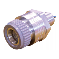
Overview of the 705 Sensor, its application in hazardous areas, and its basic components.
Explains how the catalytic sensor detects combustible gas and compensates for ambient temperature changes.
Lists available accessories for the 705 Sensor, including collecting cones, housings, and filters.
Details the purpose and fitting of the Weather Protection Housing for exposed locations.
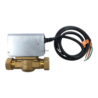
Describes the Sample Flow Housing for closed system sampling via pipelines.
Explains the Gassing Point Assembly for simplifying sensor calibration and test gas application.
Discusses the necessity and purpose of filters for sensor protection and sealing.
Details the construction and function of the stainless steel mesh filter.
Instructions for carefully unpacking the equipment and checking for damage or missing items.
Guidance on the correct orientation for sensor installation, especially in exposed locations.
Describes the Terminal Housing as a mounting base and housing for the sensor's electronic circuit.
Details the sensor's wiring connections, including color codes for sensitive, non-sensitive, and common elements.
Step-by-step instructions for installing the 705 Sensor, including safety precautions and thread engagement.
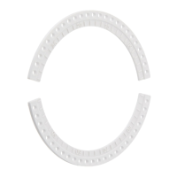
Steps to fit the Collecting Cone Assembly to the sensor, including filter installation.
Instructions for fitting the Weather Protection Housing to the sensor.
Procedure for fitting the Sample Flow Housing to the sensor, including anti-seize compound application.
Guidance on fitting the filter and keeping it clean from contaminants.
Overview of maintenance tasks including cleaning, gasket replacement, and gassing the sensor.
Procedure for cleaning the sensor and accessories using methanol, with safety precautions.
Method for gassing the sensor when no accessories are fitted, suggesting a plastic bag.
Instructions for gassing sensors fitted with specific accessories, with cautions on nozzle pressure and wind.
Procedure for gassing a sensor equipped with a Sample Flow Housing.
Lists part numbers for different Terminal Housings and their specifications.
Lists part numbers for common maintenance spares like sensor assemblies and accessories.
Details the UL certification for Class 1, Division 1, Groups B, C, and D.
Specifies the drive current required for the sensor, supplied from the control equipment.
Indicates where to find information regarding line resistance requirements.
Specifies the operating and storage humidity limits for the sensor.
Provides physical dimensions and weight for the sensor and its accessories.
Details the type of terminals used for cable connection and their specifications.
| Brand | Honeywell |
|---|---|
| Model | 705 |
| Category | Accessories |
| Language | English |