Do you have a question about the Honeywell DT8035 Dual Tec and is the answer not in the manual?
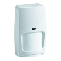
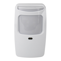
Guidance on choosing the optimal location for the motion sensor, avoiding direct sunlight and obstructions.
Instructions for physically mounting the sensor to the wall or corner using provided hardware.
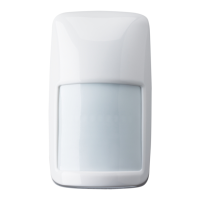
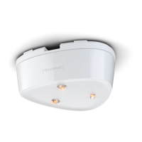
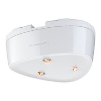
Overview of sensor features, DIP switch settings, and adjustment controls like Look Down and MW Sensitivity.
Details on connecting the sensor wires, including terminal identification and wire gauge specifications.
Procedure for testing sensor functionality, LED indicators, and adjusting microwave range for optimal performance.
Visual representations of the sensor's detection zones and patterns from top and side views.
Explanation of the sensor's alarm relay states (Normal, Intrusion, Trouble) and their corresponding contacts.
Guidance on diagnosing and resolving common sensor issues, including LED indicators and trouble conditions.
Technical details, certifications, and regulatory statements for the motion sensor.
| Type | Motion Detector |
|---|---|
| Coverage | 90° |
| Tamper Switch | Normally Closed (NC) |
| Microwave Frequency | 10.525 GHz |
| Detection Method | PIR, Microwave |
| Detection Range | Up to 35 feet |
| PIR Detection Range | 35 ft (10.6 m) |
| Power Supply | 9 to 15 VDC |
| Current Draw | 25mA max |
| Current Consumption | 25mA max |
| Alarm Relay | Form C, 28V DC, 125mA max |
| Temperature Range | -10°C to +55°C |
| Operating Temperature | -10°C to +55°C |
| Mounting Height | 6.5 to 8.5 feet (2 to 2.6 m) |