Do you have a question about the Honeywell Dual Tec DT-500 and is the answer not in the manual?
| Microwave Frequency | 10.525 GHz |
|---|---|
| Coverage Area | 50 ft x 50 ft (15m x 15m) |
| Current Consumption | 25mA (Standby), 35mA (Alarm) |
| Technology | PIR and Microwave |
| Detection Range | 15 m |
| Power Supply | 9-15 VDC |
| Tamper Output | Normally Closed (NC) |
| Operating Temperature | -10°C to +55°C |
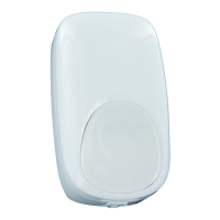
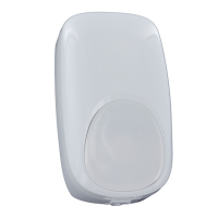
| Type | Dual Technology Motion Detector |
Choose the optimal mounting height for animal immunity.
Gently pull the sensor housings apart at the base.
Carefully remove the printed circuit board from the housing.
Break out knock-outs and mount the rear housing.
Wire the unit observing proper polarity, using 14-22 AWG wire.
Apply power, allow warm-up, then test the sensor's detection.
Sensor tracks motion; LED indicates alarm after 2-4 steps.
Red LED latches ON if microwave signals fail or system is not working.
Mount at 7'6" and ensure animals stay 6' away.
Ensure level mounting and clear line-of-sight for optimal immunity.
Specifies the sensor's detection range and PIR fields of view.
Details power requirements, alarm/tamper ratings, and RFI immunity.
Lists dimensions, weight, and product approval listings.