Do you have a question about the Honeywell DT8012F4 and is the answer not in the manual?
Optimal range at 2.3m, clear line-of-sight, avoid windows, machinery, heat sources, and pets up to 45kg.
Configure look-down and pet immunity features for optimal detection and pet handling.
Use flashlight beam on sensor lens to re-activate walk test mode if it expires.
Understand top and side view detection zones, including specific zone types (Look-down, Lower, Intermediate, Long).
Describes alarm relay normal, intrusion, and trouble status conditions.
Identifies self-test failure, microwave supervision, PIR self-test, and temperature compensation issues with solutions.
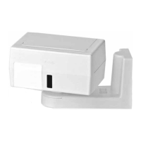
Lists available swivel mount brackets for installation flexibility and tamper security.
Details range, power, alarm relay, tamper, frequencies, RFI, temperature, dimensions, and weight.
| Operating Voltage | 9-16VDC |
|---|---|
| Voltage Range | 9-16 VDC |
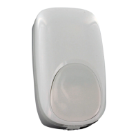
| Color | White |
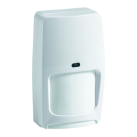
| Detection Method | Dual Technology (PIR + Microwave) |
| Material | Plastic |
| Compatibility | Compatible with most security systems |