MODEL
RANGE
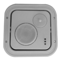
Switch S4
MIRROR
Selector
DT-906
61 m (200')
OPEN*
200'*
DT-906
37 m (120')
CLOSED
120'
DT-900
27 m (90')
OPEN*
90' *
DT-900
15 m (50')
CLOSED
50'
SENSITIVITY
S3
HIGH
H
NORMAL
N*
LOW
L**
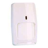
DT·900 Series
DUAL TEC
®
Motion Sensor for Commercial
and
Light Industrial Applications - Installation Instructions
Step 1
Select mounting height.
Step 2
Carefully push screwdriver into slots
to
disengage latches and open top
cover.
Step 3
Firmly insert screwdriver into slot in arrow
and rotate PIR Mirror Selector
to the
correct range.
Step 4
Set switch S4 to establish microwave
range.
Step 5
Locate correct sensor range scale
and
rotate Vertical Adjustment Screw
until the
diamond corresponds to the
sensor
mounting height (coarse
adjust).
NOTE: Fine adjust may be needed during
walk-test. See Supplemental Information.
Step 6
Set switch S3 to establish the sensitivity
best suited to your application.
*Factory default setting.
**Not connected
**Not recommended for DT-906
Step 7
Select INFORMER®
mode with switch
S2 if desired. (See Supplemental
Information).
Step 8
Carefully push screwdriver into slot to
disengage latch and remove
bottom
cover.
Step 9
Unfasten screws and remove mounting
plate from sensor.
Step 10
Attach mounting plate to wall at
desired
height, using four fasteners
(not
supplied).
Step 11
Install M5 (#10) screw in wall 1.9 cm
(3/4") below mounting screw, as
shown,
for tamper activation.
1.9 cm (3/4")
Step 12
Pull about 30 cm (12") of wire from wall
through the opening in the
mounting
plate and route wire to the
terminal strip.
Step 13
Hang the sensor on the mounting
plate
hooks and fasten with the two mounting
plate screws.
Step 14
Wire the unit
as shown.
Use 2.0 - 0.3 mm
2
(14 – 22 AWG)
NOTE: Secure
wires to
mounting plate with
tie wraps.
Step 15
Loosen horizontal locking screw in
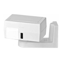
sensor support base.
Step 16
Grasp housing and rotate it to the
desired
position (coarse adjust). If
fine adjust is
needed see Steps 20 -
22.
NOTE: Reference marks
=
5° change.
Step 17
Apply power to sensor and prepare
for
walk-test.
Wait 90 seconds for power-up self-test
to run. All LEDs will flash.
PIR ALARM MW
(Green) (Red) (Yellow)
NOTE
: LEDs flashing after 90 sec.
=
defective
Step 18
Turn the microwave potentiometer
counterclockwise to decrease the
microwave range to minimum.
During walk-test, gradually turn the
potentiometer clockwise increasing
microwave sensitivity until the
desired
range is obtained.
Step 19
Walk-test the sensor to check for
adequate detection coverage and to
verify the sensor is fully functional.
Two to
four normal steps should
make the LEDs
light and trigger an alarm.
NOTE: If an on-going self-test problem, mask
condition or an INFORMER condition occurs, the
LEDs display a pattern that identifies the
trouble.
See Supplemental Information
(Table 3).
NOTE: When there is no motion in the
detection area, all three LEDs should be off.
Step 20
For finer horizontal adjustments,
loosen
the PIR horizontal fine locking
screw on
PCB.
Step 21
Rotate horizontal fine adjust knob to
the
desired position.
NOTE: Fine adjustment allows for small
changes (3 degrees right or left) between
coarse settings.
Step 22
Tighten horizontal fine locking screw
on
PCB.
Step 23
Tighten horizontal locking screw in
sensor support base.
Step 24
Remove jumper at J5, on the PCB,
to
disable the LEDs after walk-testing.
Step 25
Complete installation by closing top
cover and replacing bottom cover.
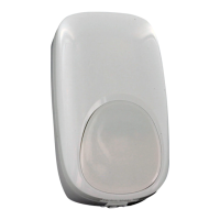
DT‐906
DT‐900
30 cm (12”) minimum
4 m (12’)
2 m (6’)
Optimal