Condition of LEDs
with No Motion
PIR
A
LARM
MW
(Green) (Red) (Yellow)
Reaction of LEDs
to Walk-Test
PIR ALARM MW
(Green) (Red) (Yellow)
Type of
Possible
Problem
Causes
(Pattern disappears)
MW environmental problem
IMBALANCE
MW range too long
PIR was blocked
RATIO
IMBALANCE
PIR range too short
PIR aimed wrong
PIR not reporting
(Pattern disappea rs)
RATIO
IMBALANCE
PIR environmental problem
PIR unstable
MW range too short
RATIO
MW range too short
IMBALANCE
MW not reporting
Operating Mode
Alert
Local Test
Standby
Remote Test
Walk Test LED's
Disabled
Enabled
Disabled
Disabled
Microwave Oscillator
On
On
Off
On
Alarm Outputs
Enabled
Enabled
Frozen
Enabled
Alarm Memory Activated
Yes
No
No
Yes
Alarm Memory Reset
Only when Entering
No
No
No
Alarm Memory Displayed
(Red LED flashing)
Disabled
Enabled
Enabled
Disabled
Trouble
Disabled
Enabled
Enabled
Disabled
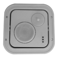
DT·900 Series DUAL TEC
®
Motion Sensor Supplemental Information
MOUNTING LOCATION
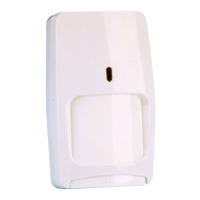
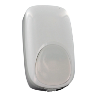
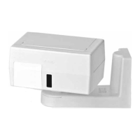
DT-906
DT-900
Aim the sensor toward the interior of the room, away from windows, moving machinery, and heating/
cooling sources.
Make sure the sensor has a clear line-of-sight to all areas you wish to protect. If the PIR is blocked, the
unit will not alarm.
TAMPER
The sensor covers and wall mounting are tamper protected. A screw must be installed in the wall
to utilize the tamper feature.
WIRING
Reverse polarity will not damage the sensor
.
Knockouts are provided to allow wire entry via 1/2" EMT or surface wiring conduit.
NOTE: For proper wiring methods, refer to the National Electrical Code NFPA 70.
INFORMER MODE
The INFORMER circuit counts the number of events registered by both the microwave and PIR
technologies, and uses the resulting ratio to determine if either technology is working properly or is
misapplied. Establish the INFORMER mode using switch S2. (See Step 7.)
Mode 1: Set S2 to position 1. In Mode 1, 32 PIR events without a microwave event will cause the
unit to go into PIR INFORMER. 128 microwave events without a PIR event will cause the unit to go
into microwave INFORMER. One LED indication does not relate to one PIR event.
Mode 2: Set S2 to position 2. In Mode 2, 16 PIR events without a microwave event will cause the
unit to go into PIR INFORMER. 16 microwave events without a PIR event will cause the unit to go
into microwave INFORMER. One LED indication does not relate to one microwave event.
NOTE: The Mode 2 setting is not recommended. Use only if fast INFORMER activation
is required.
Trouble Memory
Disabled: To disable INFORMER function, set S2 to the open position.
If the LED pattern disappears before you see it, you can retrieve the pattern. The trouble memory feature stores the last LED pattern from
a self-test detected problem or an INFORMER condition.
When an INFORMER condition occurs, the trouble relay opens, and the LEDs display an INFORMER trouble code. The sensor performs
a self-test within the hour to determine if the problem is internal.
To recover the LED pattern, first open the Top Cover (see Step 2). Using a small screwdriver, momentarily short circuit the two Self-Test
pads located on the printed circuit board (see Supplemental Information, Figure 1). The trouble LED pattern will be re-displayed.
If a self-test error is detected, the self-test LED pattern, all three LEDs flashing, replaces the INFORMER LED pattern.
Short the pads with the screwdriver again to clear the LED pattern and initiate a self-test.
If no self-test error occurs, the unit continues to display the INFORMER LED pattern and relay remains open. The problem is
misapplication. Walk-test the sensor to pinpoint the cause. (Refer to Troubleshooting Table 3.)
Anti-Mask
The DT-900 Series anti-mask feature detects attempts to block or cover the sensor by sending an active infrared beam out into the
INPUT MODES
sensor's field-of-view, at regular 8 second intervals. If the DT-900/DT-906 is blocked or covered (i.e. with a box or fabric) the beam
The DT-900 Series accommodates several international operating requirements using two operating modes-Standard mode with is reflected back to the sensor. After two consecutive reflected beams, the sensor signals a trouble condition-green and red
remote LED enable and Command Input capability or European 2-Wire CENELEC mode (INPUT 1 and INPUT 2). For Standard LEDs flash rapidly and the mask relay opens.
Mode, remove jumper J4 and install jumper J6. For CENELEC mode, remove jumper J6 (See Figure 1).
INFORMER Conditions
Table 1 Standard Mode-J6 Installed Table 2 CENELEC Mode-J6 Removed
Table 3 describes two trouble alerts which are reported by the INFORME R circuit. To use this troubleshooting matr ix:
1)
Find the trouble alert that describes the condition of the walk-test LEDs (with no motion in the area).
2)
Walk-test the sensor, carefully watching the reaction of the diagnostic LEDs.
3)
Refer to the Possible Causes column of the matrix for an explanation of the way in which the diagnostic LEDs
reacted to the walk-test.
Table 3 INFORMER
Troubleshooting Matrix
Table 4 Cenelec Functions
RATIO
TROUBLESHOOTING
Vertical Adjustment
Various mounting locations may require fine vertical adjustment (e.g. uneven walls or floors, etc.). During the walk-test, if the PIR is short-
ranged, turn the Vertical Adjust Screw counterclockwise. If the PIR is over-ranged, turn the Vertical Adjust Screw clockwise.
(See Step 5.)
Self-Test
The sensor microcontroller automatically performs a series of self-tests in the following instances: When the unit is powered up, when
tests are installer initiated, upon Command Input, or every hour during normal operation. A self-test error causes the Trouble relay
to open and all 3 LEDs flash unt il the problem is corrected. If the problem persists and the LE Ds continue to flash, the unit is defective
LED Legend: = LED is Flashing Slow =LED is OFF
and must be returned fo
air.
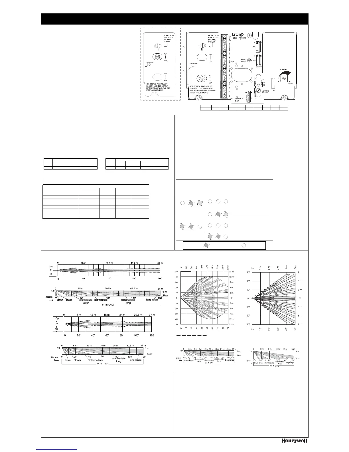
DETECTION PATTERNS
Patterns for: DT-900
Patterns for: DT-900
Pattern for: DT-906
TOP VIEW
27 m (90') Range 15 m (50') Range
61 m (200') Range
Barrier Lens-All Zones
TOP VIEW
TOP VIEW
Wide Angle Lens
Wide Angle Lens
SIDE VIEW
Barrier Lens-All Zones
Pattern for: DT-906
TOP VIEW
37 m (120') Range Barrier Lens-All Zones
Indicates Detection Area
SIDE VIEW
Barrier Lens-All Zones
SIDE VIEW
SIDE VIEW
Wide Angle Lens
Wide Angle Lens
PRODUCT SPECIFICATIONS IMPORTANT: DT-900 Series sensors should be tested at least once each year to ensure proper operation.
Range:
DT-906
37 m x 3 m / 61 m x 5 m
120' x 10' / 200' x 15'
DT-900
15 m x 12 m / 27 m x 21 m
50' x 40' / 90' x 70'
Alarm relay:
Energized Form C; 25 VDC, 125 mA
22 ohm series protection resistor
Power requirements:
10 - 15 VDC; 50 mA (max) at 12 VDC
AC Ripple: 3V peak-to-peak at nominal
12 VDC
PIR white light immunity:
6500 Lux
RFI immunity:
30 V/m, 10 MHz – 1000 MHz
Trouble relay:
De-energized Form B;
(Normally closed); 30 VDC, 25 mA
Mask relay:
De-energized Form B
(Normally closed)
30 VDC, 25 mA
Input 1 & 2:
Self-test initiate
Active low 0 to 1.5V
Inactive high 5 to V+
Sensitivity:
2 – 4 steps within field of view
Tampers:
Wall, top & bottom covers
30 VDC, 25 mA (NC)
PIR fields of view:
61 m (200’) Range
2 long
6 intermediate long
4 intermediate
4 intermediate lower
8 lower
2 down
37 m (120’) Range
6 long
4 intermediate long
4 intermediate
8 lower
2 down
27 m (90’) Range
18 long
18 intermediate long
16 intermediate
12 intermediate lower
8 lower
2 down
15 m (50’) Range
18 long
16 intermediate long
12 intermediate
8 lower
2 down
Microwave frequencies:
X band
Operating temperature:
0° to 49° C / 32° to 120° F
Relative Humidity:
5% to 95% relative humidity
(non-condensing)
Dimensions:
20 cm x 16.5 cm x 15.2 cm
8” x 6 1/2” x 6”
Weight:
1.36 kg / 3 pounds
Packaged product:
1.6 kg / 3.5 pounds
Approvals/listings:
FCC certified
Industry Canada
UL listed
ULC listed
FEDERAL COMMUNICATIONS COMMISSION STATEMENTS
The user shall not make any changes or modifications to the equipment unless authorized by the Installation Instructions or User's Manual. Unauthorized changes or
modifications could void the user's authority to operate the equipment.
CLASS B DIGITAL DEVICE STATEMENT: This equipment has been tested to FCC requirements and has been found acceptable for use. The FCC requires the
following statement for your information:
This equipment generates and uses radio frequency energy and if not installed and used properly, that is, in strict accordance with the manufacturer's instructions,
may cause interference to radio and television reception. It has been type tested and found to comply with the limits for a Class B computing device in accordance
with the specifications in Part 15 of FCC Rules, which are designed to provide reasonable protection against such interference in a residential installation. However,
there is no guarantee that interference will not occur in a particular installation. If this equipment does cause interference to radio or television reception, which can
be determined by turning the equipment off and on, the user is encouraged to try to correct the interference by one or more of the following measures:
• Reorient the receiving antenna until interference is reduced or eliminated.
• Move the radio or television receiver away from the receiver/control.
• Move the antenna leads away from any wire runs to the receiver/control.
• Plug the receiver/control into a different outlet so that it and the radio or television receiver are on different branch circuits.
• Consult the dealer or an experienced radio/TV technician for help.
INDUSTRY CANADA CLASS B STATEMENT
This Class B digital apparatus complies with Canadian ICES-003.
Cet appareil numérique de la classe B est conforme à la norme NMB-003 du Canada.
FCC / IC STATEMENT: This device complies with Part 15 of the FCC Rules, and RSS210 of Industry Canada. Operation is subject to the following two conditions:
(1) This device may not cause harmful interference, and (2) This device must accept any interference received, including interference that may cause undesired
operation.
Cet appareil est conforme à la partie 15 des règles de la FCC & de RSS 210 des Industries Canada. Son fonctionnement est soumis aux conditions suivantes: (1) Cet
appareil ne doit pas causer d’interférences nuisibles. (2) Cet appareil doit accepter toute interférence reçue y compris les interférences causant une réception indésirable.
DUAL TEC and INFORMER are registered trademarks of Honeywell International Inc.
Copyright 2012 Honeywell International Inc. All rights reserved.
P/N 5-051-344-00 Rev H
Feet 6 8 10 12 14 50 90 120 200
Meters 1.8 2.4 3 3.7 4.3 15 27 37 61
Input Condition Operating Mode
HIGH/Not connected LOW Alert Local Test Standb
 Loading...