2
5821-007-V0
2
1
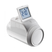
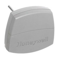
ON
WIRES
MOUNTING
PLATE
HOLES (2)
(ANTENNA
REMOVED
FOR CLARITY)
LOCKING
TAB
POST (2)
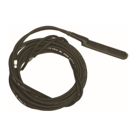
PROBE
PROBE
TERMINALS
TESTING THE DETECTOR
Do the following to determine a good RF transmission path and again after installation is completed. To test,
1. Activate the control panel’s test mode.
2. Activate the detector by removing and replacing the cover. The system’s keypads should beep and each zone the
5821 is programmed for will be displayed.
3. Exit the control’s test mode [User Code + OFF].
MAINTAINING PROPER OPERATION
To maintain the detector in proper working condition, it is important that you observe the following:
• Replace the battery when a low battery condition is reported.
• Units should never be relocated without the advice or assistance of the alarm service company.
SETTING THE OPERATING MODE
Table 1 provides a list of the various operating modes of the 5821 with the respective Loop and DIP Switch settings for
each. Note that Cold Temp Sensing can be used in combination with any of the other operating modes. To use the
transmitter to monitor two different conditions, you must program each loop used on the 5821 as its own zone, and
you must set the DIP Switches as shown for the combination functions in Table 1.
TABLE 1: OPERATING MODE SETTINGS
Sensing
Probe
to
Term. Block
Loop No.
DIP
1
DIP
2
Flood
FP280 or
470PB
3
---
ON
Cold & Flood
FP280 or
470PB
1 – Cold
3 - Flood
--- ON
Cold --- 1 --- ---
Hot --- 2 --- ---
Warm --- 2 ON ---
Freezer T280R 2 --- ON
Refrigerator T280R 2 ON ON
Cold & Hot ---
1 - Cold
2 - Hot
--- ---
Cold & Warm ---
1 - Cold
2 – Warm
ON ---
Cold & Freezer T280R
1 - Cold
2 - Freezer
--- ON
Cold & Refrigerator T280R
1 - Cold
2 - Refrigerator
ON ON
When the 5821 is used with either external probe, an open-circuit or a short-circuit of the probe’s wiring results in an alarm on that
loop, and a trouble condition on all other programmed loops.
Shunted by 2.2MΩ resistor. Use a maximum wire length of 48 inches between the 5821 and the 470PB probe.
Disengage mounting plate by inserting a
screwdriver into the locking tab release
window and press against locking tab, while
sliding the mounting plate upward until free.

 Loading...