2
MOUNTING THE DETECTOR
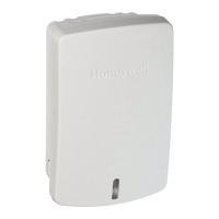
You can mount the 5821 on a wall or ceiling within the
protection area. The following notes apply:
• The 5821 may be installed in any direction.
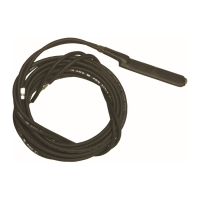
• When used in-conjunction with the ADEMCO 470PB flood
sensor probe, use no more than 48 inches of wire from the
5821 to the flood sensor and connect the termination
resistor across the probes terminals.
• When used in-conjunction with ADEMCO T280R
temperature probe, use the shortest wire possible (less
than 96 inches) to improve the signal integrity.
• Although the unit can be mounted directly to a surface, we
recommend that the mounting plate be used for ease of
removal for servicing if necessary. Avoid mounting the
detector near heat generating devices (e.g. ovens, heat
vents, furnaces, boilers) or to a metal cabinet or surface.
Wireless Transmission Path Test
A good RF transmission path must be established from the
proposed mounting location before permanently installing the
detector. To determine that there is good signal reception from
the proposed location, perform the test procedure described in
TESTING THE DETECTOR section.
Once a good RF transmission path is confirmed, mount the
detector as follows, referring to Figure 1.
5821-001-V0
LOCKING
TA B
RELEASE
WINDOW
COVER PRY-OFF SLOT
MOUNTING
PLATE
HOLES (2)
OBSERVE POLARITY
LOCKING
TAB
WIRES
MOUNTING PLATE
CASE
COVER
RETAINING
HOOKS
(3)
POST (2)
5821-002-V1
LOOP
TERMINALS
BATTERY
CR123A
COVER
RETAINING
HOOKS (3)
ANNTENNA
DIP SWITCH
+
+
COVER
PRY-OFF
SLOT
WIRE ENTRY
HOLE
TAMPER
SWITCH
IC
CRYSTAL
+
_
21
ON
21
ON
Figure 1
To mount the detector, proceed as follows:
1. Remove the battery.
2. Disengage the attached mounting plate from the case by
inserting the blade of a small screwdriver into the locking
tab release window (see Figure 1) and pressing it against
the locking tab (also shown in Figure 1), while sliding the
mounting plate upward along the case back until free.
3. Install the mounting plate, with its two case- holding posts
pointing up (in this example), in the location selected. Use
the flat-head screws supplied.
4. For surface wiring entry, two thin "breakout" areas are
provided in the case wall (see Figure 1).
5. Attach the case back to the mounting plate by sliding the
keyhole slots in the case back down onto the mounting
plate's case holding posts. The locking tab will click as the
case back locks in place.
External Probe Wiring Connections (If used)
6. With the battery still not inserted, connect the wires to the
unit's sensor terminals (see Figure 1).
7. Install the battery.
IMPORTANT:
This detector should be used for property protection. Reliance
should not be placed on this detector for life safety. When life
safety is involved, smoke detectors MUST also be used. The
flood probe must not be painted.
TESTING THE DETECTOR
The test procedure should be performed to determine a good
RF transmission path and again after installation is completed.
To test,
1. Activate the control panel’s test mode.
2. Activate the detector by removing and replacing the
cover. The system’s keypads should beep and each
zone the 5821 is programmed for will be displayed.
3. Exit the control’s test mode (User Code + OFF).
MAINTAINING PROPER OPERATION
To maintain the detector in proper working condition, it is
important that you observe the following:
Replace the battery when the system indicates that the 5821
reported a low battery condition.
Units should never be relocated without the advice or
assistance of the alarm service company.
 Loading...