EasyManua.ls Logo

Honeywell ADEMCO 6160RF3 - User Manual

Honeywell ADEMCO 6160RF3
4 pages
Print Icon
To Next Page IconTo Next Page
Loading...
K0903V1 2/06 Rev. F
ADEMCO 6160RF
Keypad/Transceiver
Installation and Setup Guide
GENERAL INFORMATION
The ADEMCO 6160RF keypad/transceiver is a combination unit that combines the functions of the following devices:
6160 Alphanumeric Addressable Keypad
5881H RF Receiver
5800TM Transmitter Module
The 6160RF Keypad/Transceiver may be used on any control panel that supports 5800 Series wireless devices (e.g., VISTA-10P,
VISTA-15P, and VISTA-20P).
FEATURES
Supports wireless key transmitters (e.g.; 5834-4) and bi-directional transmitters (e.g.; 5804BD, 5828/5828V).
Supports wireless keys with high-security (encryption) capability (e.g.; 5804E, 5834-4).
Provides a nominal range of 200 feet for RF transmitters (some transmitters have a shorter range).
Supports RF jam detection when the receiver is enabled.
Capable of sending status signals (Armed, Ready, etc.) to bi-directional units such as 5804BD, 5804BDV and 5828/5828V.
U
L
The following 5800 series transmitters are not intended for use in UL installations: 5802, 5834-4, 5804BD, 5804BDV,
5804E, 5814, 5819, 5819BRS, 5819WHS, and 5828/5828V.
INSTALLING THE 6160RF
Locate the 6160RF in an area and at a height where it is
convenient for user operation. The 6160RF must be at least
10 ft from the control panel to ensure proper operation of the
RF receiver.
Mounting and Wiring
The 6160RF has terminal blocks for connection to power and
data wires. Removing the keypad’s case back provides
access to the terminal blocks.
The 6160RF can be surface mounted directly to walls, or to a
single- or double-gang electrical box. Follow these steps to
mount and wire the keypad:
1. Push the two case release snaps at the bottom of the
keypad with the blade of a medium screwdriver (this will
push in the release snap), then pull that side of the case
back away. Insert the screwdriver in the side of the
keypad (between the front and back case) and gently
twist to release the side locking tab. Repeat for the other
side. Refer to Figure 1 for location of the case back
release snaps and locking tabs.
ARMED
READY
MOUNTING
RELEASE
SNAPS
NOTE:
TO REMOVE REAR COVER
PUSH IN THE TWO MOUNTING
SNAPS LOCATED ALONG THE
BOTTOM OF THE KEYPAD
AND LIFT COVER UP.
6160RF-003-V1
LOCKING
TA B
Figure 1. Removing the Case Back
2. Pass the wiring from the control panel through the
opening in the case back. (see the control panel’s
instructions for proper run lengths.)
a. If surface wiring is being used, wiring may be routed
through the top or the bottom left-side breakout in the
case back. The breakouts must be punched out using
a screwdriver before mounting the case back.
b. If desired, wires may be strain-relieved to the wire tie
point on the inside of the case back with a tie wrap
(not supplied).
3. Mount the case back to a wall or to an electrical box using
the 25mm-long self-tapping screws supplied (mollies for
drywall are not supplied).
4. Connect the power and data wires from the control panel
to the terminals on the 6160RF as indicated in Figure 2
and Table 1
.
G
6160RF-002-V1
Y
+
WIRING TERMINALS
(TO CONTROL PANEL)
+
+
+
+
Figure 2 - 6160RF Wiring Details
Question and Answer IconNeed help?

Do you have a question about the Honeywell ADEMCO 6160RF3 and is the answer not in the manual?

Overview

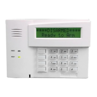
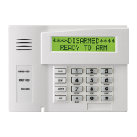
The ADEMCO 6160RF Keypad/Transceiver is a versatile combination unit that integrates the functionalities of an alphanumeric addressable keypad, an RF receiver, and a transmitter module. It is designed for use with control panels that support 5800 Series wireless devices, such as the VISTA-10P, VISTA-15P, and VISTA-20P.

Function Description:

The 6160RF serves as a primary interface for alarm systems, allowing users to arm/disarm the system, view status, and interact with various system functions. Its integrated 5881H RF Receiver enables it to receive signals from 5800 Series wireless transmitters, including standard wireless keys (e.g., 5834-4) and bi-directional transmitters (e.g., 5804BD, 5828/5828V). The 5800TM Transmitter Module allows it to send status signals (e.g., Armed, Ready) to bi-directional units like the 5804BD, 5804BDV, and 5828/5828V. A key feature is its support for wireless keys with high-security (encryption) capabilities, such as the 5804E and 5834-4, enhancing system security. The device also includes RF jam detection, which is active when the receiver is enabled, providing an additional layer of security by alerting to attempts to block wireless communication.

Important Technical Specifications:

  • Physical Dimensions: 5-3/8" H x 7-3/8" W x 1-1/4" D (137mm x 187mm x 32mm).
  • Wiring: Utilizes a 4-wire connection (Data In, Aux Pwr GND, Aux Pwr, Data Out) with specific color codes (Green, Black, Red, Yellow).
  • RF Range: Provides a nominal range of 200 feet (60.9 m) for RF transmitters, though some transmitters may have a shorter range.
  • Frequency: Operates at 345 MHz.
  • Current Consumption:
    • Standby: 50mA
    • Backlighting on and Sounder on: 150mA
  • Display: Features a 2 x 16 alphanumeric supertwist LCD, which is backlit for visibility.
  • Sounder: Equipped with a Tone Generator Integrated Circuit, producing distinct tones for fire alarms (loud pulsing tone) and burglary/audible panic alarms (continuous tone).

Usage Features:

The 6160RF is designed for user-friendly operation and flexible installation. It can be surface-mounted directly to walls or installed on single- or double-gang electrical boxes. The device requires proper placement, at least 10 feet from the control panel, to ensure optimal RF receiver performance.

Programming the 6160RF involves a series of steps accessible by simultaneously pressing the [1] and [3] keys within 60 seconds of power application. Key programming parameters include:

  • Keypad Address: A two-digit address (00-31) assigned to the keypad, which must align with the control panel's acceptable addresses. For VISTA-40 panels and above, the 6160RF's partition assignment must match the RF keypad partition assignment programmed in field (1*48).
  • Receiver Enable: Option to enable (1) or disable (0) the receiver. Enabling is necessary if RF transmitters or wireless keypads are programmed into the control panel and no other receivers are enabled.
  • Receiver Address: A two-digit address (00-30) for the receiver, if enabled, again requiring alignment with the control panel's acceptable addresses.
  • House ID: A two-digit ID (01-31) that can be programmed if the receiver is disabled. If the receiver is enabled, the 6160RF uses the House ID programmed in the control panel. This ID is crucial for wireless devices to communicate with the 6160RF.
  • High Security Mode: Option to enable (1) or disable (0) high-security mode. When enabled, the 6160RF only recognizes encrypted devices. When disabled, it processes both encrypted and non-encrypted commands.

The device supports the activation of high-security (encrypted) devices, with a maximum capacity of 8 such devices. Attempting to enroll more than 8 devices will result in an "EXCEEDED NUMBER" message. A procedure is also available for disabling high-security devices, which is particularly useful if a wireless key is lost. This process involves deleting all high-security devices from the 6160RF and, if desired, from the control panel.

Maintenance Features:

The 6160RF includes troubleshooting indicators to assist with maintenance. Error messages such as "Low Bat (with zone no.)" indicate a low battery in a wireless device, prompting replacement of the battery or the transmitter itself. "Open Ckt" suggests no data is being received from the control panel, requiring verification of the yellow data wire connection. "Check 100" or "Check 1xx*" (where xx is the device address) indicates that the control panel does not recognize the 6160RF receiver or that another device on the keypad terminals is not communicating. Corrective actions typically involve verifying wiring connections (yellow and green wires), checking the control's receiver address, and ensuring proper communication between all connected devices.

The keypad's case back is removable for access to terminal blocks, facilitating wiring and installation. The top of the keypad attaches first, followed by the bottom section, which snaps securely into place. A protective film on the LED panel should be peeled off, and keypad labels installed as required during setup.

Honeywell ADEMCO 6160RF3 Specifications

General IconGeneral
BrandHoneywell
ModelADEMCO 6160RF3
CategoryKeypad
LanguageEnglish

Related product manuals