ADEMCO 61
ADEMCO 61ADEMCO 61
ADEMCO 616
66
60
00
0P
P
P
P
AlphaProx
AlphaProxAlphaProx
AlphaProx K
K K
Keypad
eypadeypad
eypad
I
NSTALLAT
I
ON AND SETUP GU
I
DE
GENERAL INFORMATION
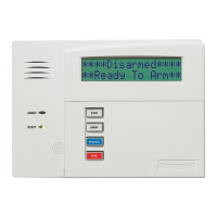
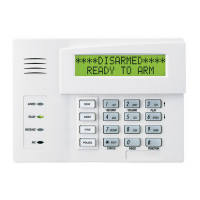
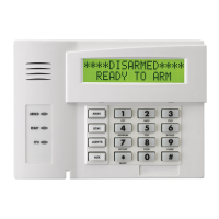
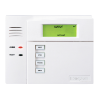
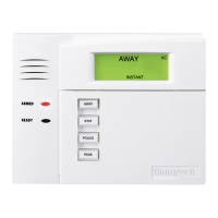
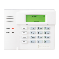
The ADEMCO 6160PX is an addressable Remote Keypad with a built-in Proximity Reader, and is intended for use
with ADEMCO control panels.
Basic features of the Keypad
• 2-line Alpha display
• Backlit Display (programmable as permanent on
some controls; see the control's instructions for
details)
• Continuously Backlit Keys for convenience
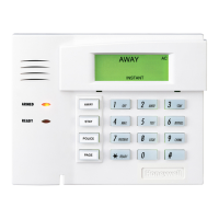
• Programmable Function Keys
• Built-in Sounder (speaker)
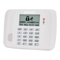
• Arm/Disarm via Prox Tag
• LED Indicators for Armed and Ready-To-Arm
• Supervised by control panel (if supported)
• Uses two keypad addresses
Installation Notes
• The Keypad can only be used on addressable systems
and must be set for address 00-30 (16-23 for
VISTA-15P / VISTA-20P and VISTA-21iP controls).
• The Prox Reader uses an additional keypad address,
which must be enabled at the control panel (see
control panel installation instructions for allowable
keypad addresses).
• The partition used for the Keypad, Prox Reader, and
user security code must be the same.
• The Prox Tags will only arm and disarm one
partition. The Prox Reader cannot be used to perform
global arming operations.
• For optimal performance, use only the Prox Tags
provided. For additional Prox Tags, order
PROXTG-BK (Black) or PROXTG-GY (Gray).
MOUNTING AND WIRING
The Keypad can be surface mounted directly to a drywall, or to a single- or double-gang electrical box.
1. Push the two case release snaps at the bottom of the Keypad
with the blade of a medium screwdriver, then pull that side
of the case back away. Insert the screwdriver in the side of
the Keypad (between the front and back case) and gently
twist to release the side locking tab. Repeat for the other
side. Refer to Figure 1 for location of the case back release
snaps and locking tabs.
2. Route wiring from the control panel through the opening in
the case back.
3. Mount the case back to a wall or electrical box.
4. Wire directly from the Keypad’s terminal block to the
terminal block on the control panel. (See Wiring Table
below). Connect only the red and black Aux. Power
connections at this time.
Do not connect the ECP Data In or Data Out until directed
to do so. If the keypad’s Prox Reader detects the presence
of ECP Data In and Out connections during address
programming mode, it will exit to “normal” mode.
NOTE: No more than one wire per terminal may be
connected. If daisy-chained configuration is required, pigtail
wires together so that only one wire is terminated under the
screw. Use 16-24 AWG wire only!
NOTE:
TO REMOVE CASE BACK
PUSH IN THE TWO MOUNTING
SNAPS LOCATED ALONG THE
BOTTOM OF THE KEYPAD
AND LIFT UP.
6150-006-V0
RETAINING
SNAPS
ARMED
READY
LOCKING
TA B
Figure 1. Removing the Case Back
Wiring Table
Keypad Control Panel Wire Color
▲G
Data In Green
– – Aux Pwr (GND) Black
+ + Aux. Pwr Red
▼Y
Data Out Yellow
See the control panel’s Installation and Setup Guide for
more complete details.
5. Reattach the Keypad to its case back.
6. If the Keypad and Prox Reader addresses have not yet been programmed, refer to the Setting the Keypad and
Prox Reader Addresses section and set the two addresses.
7. After the Keypad and Prox Reader addresses have been programmed, remove the Keypad from its back plate
again (see step 1 above) and connect the green and yellow (data in/data out) wires from the control.
8. Reattach the Keypad to its case back.