K6206V1 6/06 Rev. B
ADEMCO
ADEMCO ADEMCO
ADEMCO 6151
61516151
6151
KEYPAD
KEYPADKEYPAD
KEYPAD
With Built-in Single-Zone Expander
INSTALLATION AND SETUP GUIDE
GENERAL INFORMATION
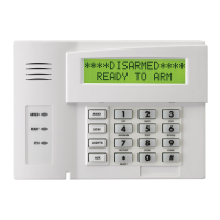
The 6151 is a general-purpose keypad that provides
one 2K EOLR zone. The general features of the 6151
can be used with any Honeywell control panel that
supports the 6150 keypad. To utilize the zone feature
of the 6151, the control panel must be capable of
supporting the 4219 ECP zone expander module.
Depending on the keypad option selected, the zone can
either be configured as EOLR or double-balanced
supervised zone. Check the control panel’s Installation
Guide for the supervision type(s) supported.
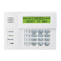
KEYPAD DISPLAYS AND LEDS
The 6151 has the following features:
• Large backlit, fixed word LCD.
• 16 large telephone-style backlit keys.
The following table shows the LEDs and their
functions:
LED Function
ARMED
(Red)
Lights when the system is armed in any
mode.
READY
(Green)
Lights when the system is ready to be
armed.
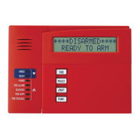
FUNCTION KEYS AND LABELS
The keypad also features four function keys. These
keys may be programmed for panic alarms or other
special functions such as single button arming, macros,
device activations, etc. See the control's instructions
for details.
The A, B, C, and D keys must be pressed and
held down for at least two seconds to activate
their programmed panic functions.
A set of adhesive labels with typical panic symbols is
provided. Place the appropriate label in the indented
area on each key, so that the user can easily identify
each key’s function.
BUILT-IN SOUNDER
The built-in sounder has the following functions:
• Produces warning sounds during alarm and trouble
conditions, and also during entry/exit delay periods.
• Provides acknowledgment tones when keys are
pressed, and confirmation tones for successful
command entries.
ZONE–INPUTS
The 2K EOLR zone has a 300mS response. A local
programming option allows selecting conventional
EOLR type or double-balanced type. The double-
balanced zone type supports up to 10 sensors.
CASE TAMPER
U
UU
U
L
LL
L
For UL (and ETL) installations, the front case tamper
must be disabled.
An on-board tamper switch detects removal of case
front from case back, and removal of the case back
from its mounting surface. A local programming
option allows you to disable the detection of a tamper
condition.
The factory default for this feature is disabled.
For tamper protection, an additional mounting screw
must be used in the case back, as shown in Figure 2.
When the 6151 is used in the addressable mode, it will
report a tamper condition to the control panel as a
4219 case tamper when the zone feature is enabled, or
as a general keypad tamper when the zone feature is
disabled. This feature should be enabled for a more
secure installation or when the on-board zone is used.
On newer control panels (e.g., Vista-20P and
Vista-12/48 series) the tamper will be reported
using the ECP address assigned to the Zone
Expander. Note that the tamper feature will
function only if the zone expander has been
enabled; Zone 96 can then be used as a
keypad panic.
The 6151 will not support general keypad
tamper reporting when set to the non-
addressable mode (keypad address 31). In
the non-addressable mode, tamper will be
reported as if it were a “C” function key/zone
96. Program this zone as a Type 5 Day/Night
(trouble by day/alarm by night) zone for
proper reporting. Also, not all control panels
support general keypad tamper reporting.
Check with the control panel’s instructions.
MOUNTING AND WIRING
The 6151 has terminal blocks for connection to keypad
power, data wires and sensor/contact zone wires.
Removing the keypad’s case back allows access to
these terminal blocks.
The 6151 can be surface mounted directly to walls, or
to a single- or double-gang U.S. style electrical box.
Follow these steps to mount and wire the keypad:
1. Detach the case back as follows:
Push the two case release snaps at the bottom of
the keypad with the blade of a medium
screwdriver (this will push in the release snap),
then pull that side of the case back away. Insert
the screw-driver in the side of the keypad
WWW.DIYALARMFORUM.COM
WWW.DIYALARMFORUM.COM