ÊK5305-1QG0Š
K5305-1QG 1/09 Rev. A
2 Corporate Center Drive, Suite 100
P.O. Box 9040, Melville, NY 11747
Copyright © 2009 Honeywell International Inc.
www.honeywell.com/security
VISTA-20P / VISTA-20PSIA and VISTA-15P / VISTA-15PSIA
Quick Installation Guide
(FOR DOCUMENTATION AND ONLINE SUPPORT: http://www.security.honeywell.com/hsc/resources/MyWebTech [see instructions K5305-1V7 or higher])
2. Connect Devices, Zones, Sounder, and Phone Line.
Refer to the Wiring Diagram on the reverse side for connection information. NOTE: This system uses a range of reserved addresses for each type of device.
1. Connect keypads and other addressable devices to the ECP terminals 4-7.
Refer to the wiring chart below for wire sizes and maximum wire run lengths.
Wire Chart For Devices Drawing Aux Power From The Control (12V+ & 12V–)
Wire TOTAL CURRENT OF ALL DEVICES CONNECTED TO A SINGLE WIRE RUN
Size 50 mA or less 100 mA 300 mA 500 mA 600 mA
#22 900ft (274m) 450ft (137m) 150ft (46m) 90ft (27m) 75ft (23m)
#20 1400ft (427m) 700ft (213m) 240ft (73m) 140ft (43m) 120ft (37m)
#18 1500ft (457m) 1100ft (335m) 350ft (107m) 220ft (67m) 170ft (52m)
#16 1500ft (457m) 1500ft (457m) 550ft (168m) 350ft (107m) 270ft (82m)
The length of all wire runs for both partitions combined must not exceed 1500 feet (457m) when unshielded quad
conductor cable is used (750 feet if shielded cable is used).
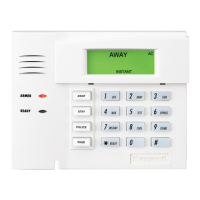
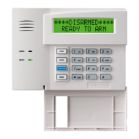
Standard Keypads (6150 / 6160 series)
• Set each keypad’s address (16-23) accordingly. Address 16 is reserved for the first keypad and is
always enabled in the control.
• Use data fields *190-*196 to enable keypads and set their sounding options.
Expander Modules (4219, 4229)
• Set each module’s address (07-11) using the module’s DIP switches.
• Use *56 Menu mode to program zone characteristics.
Touchscreen Keypads (6270 / 6271 series, 8132 series)
• Set each touchscreen’s address accordingly (01, 02, 05, 06) and enable in field ∗189.
• Make sure the auxiliary current drain is within the control’s limitation. Otherwise use an external
power supply to power the touchscreen keypads.
Relay Modules (4204)
• Connect desired field wiring to the module’s relay contact terminals.
• Set each module’s address (12-15) using the module’s DIP switches.
• Use ∗79 / ∗80 Menu modes to enter each device address and define functions.
RF Receiver (5881, 5883, RF Keypad)
• Set the receiver’s address to 00 using the module’s DIP switches.
• If using wireless keypads, set field ∗24 RF House ID Code appropriately.
If receiver is mounted remotely, note the following:
• Do not locate the receiver or transmitters on or near metal objects. This will decrease range and/or
block transmissions.
• Do not locate the RF receiver in an area of high RF interference (indicated by frequent or
prolonged lighting of the receiver’s LED; random flicker is OK).
• Do not locate RF receiver closer than 10 feet from any keypads.
Communication Device (7847i, 7845GSM, 7845i-GSM)
• Set the communication device to address 03.
• Use ∗29 Menu mode to enable and program the device.
AVS System
• If used, follow the installation instructions provided with the module.
• Connect the AVS module to the control’s ECP terminals and connect all other
ECP devices to the
AVS module’s ECP terminals.
• Set the AVS address using its DIP switches: V15P = 08; V20P = 11
• Use the desired AVS Quick Program Command to set pre-defined options:
installer code + 0-3: enable AVS operation
installer code + 0-4: enable AVS and enable panel sounds on AVST speaker
• Use field ∗55 Dynamic Signaling Priority to select the desired reporting paths.
2. Connect hardwire zones to the appropriate zone terminals 8-20.
3. On-Board Trigger Connections
• Connect field wiring to the appropriate trigger pin using the SA4120XM-1 cable (if using 1361X10
transformer) or the 4-wire cable supplied (N4632-4).
• Trigger outputs are normally high, and go low upon programmed condition.
• Outputs can be set for inverted operation (low, go high) using *79 Menu mode.
• Use ∗79/∗80 Menu modes to program the trigger outputs.
4. Install Wireless Zone Transmitters.
• Use ∗56 Menu mode to program wireless zones and enroll the transmitters.
• Use the Go/No Go Test mode to verify adequate signal strength from each transmitter location:
system “Ready to Arm,” enter Installer code + [#] + 4, then fault each transmitter and listen for 3
beeps at the keypad and the zone display. Exit mode: user code + [1] (OFF).
5. Connect the external sounder to terminals 3 and 4.
• If supervised output desired, see Sounder Supervision wiring diagram on reverse side, and set field
∗91 Option Selection for Bell Supervision.
6. Connect the phone line using terminals 21-24.
• Use an RJ31X jack as shown in the diagram on reverse side.
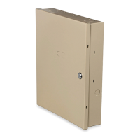
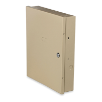
1. Mount the Control.
1. Mount the control cabinet to a sturdy wall in a clean, dry area, which is not readily accessible to the
general public, using fasteners or anchors (not supplied) with the four cabinet mounting holes.
2. Remove cabinet door, then remove the lock
knockout from the door. Insert the key into the
lock
3. Position the lock in the hole, making certain that
the latch will make contact with the latch bracket
when the door is closed. When correctly
positioned, push the lock until the snap tabs hold
it securely.
The cabinet can be secured without a lock by
using 2 screws in the cover's edge.
CABINET DOOR
BOTTOM
LOCKED
UNLOCKED
cab_lock_snap-001-V0
ADEMCO
ADEMCO
PUSH
SNAP
TAB
SNAP
TAB
PUSH
ON LOCK
UNTIL IT
IS SEATED
SECURELY
STEP 2STEP 1
CHECK
POSITION
Installing the Cabinet Lock
4. Before installing the cabinet's contents, remove the cabinet knockouts needed for wiring entry. Do not
remove the knockouts after the PC board has been installed.
5. Mount the PC Board. Refer to the diagram below.
+
+
CIRCUIT
BOARD
INSERT THE TOP OF THE
CIRCUIT BOARD INTO THE
SLOTS AT THE TOP OF THE
CABINET
DETAIL B
SIDE VIEW
OF MOUNTING CLIPS
DETAIL A
SIDE VIEW
OF BOARD SUPPORTING
SLOTS
CIRCUIT
BOARD
cb_mount-001-V1
CABINET
CABINET
HANG TWO SHORT MOUNTING CLIPS
(PROVIDED) ON THE RAISED CABINET TABS.
SECURE THE BOARD TO THE
CABINET WITH THE ACCOMPANYING
SCREWS
Mounting the PC Board
3. Connect the Transformer & Battery.
1321 Transformer (1321CN in Canada)
• Do not plug the transformer into the AC outlet until all wiring connections to the control are complete. As
a safety precaution, always power down the control when making such connections.
1361X10 Transformer
(required if using Powerline Carrier devices)
1. Splice one end of a 3-conductor cable to the wire ends of the SA4120XM-1 cable.
2. Connect the SA4120XM-1 cable plug to the 8-pin connector on the control.
3. Connect the other end of the 3-conductor cable to the 1361X10 Transformer.
Canadian Installations: For Powerline Carrier Devices, use the PSC04 X-10 Interface and trigger
connector pins.
Battery Connections
• After all connections to the control are completed and after AC power has been applied, connect the
red and black flying leads on the control board to the battery.
• This control will not power-up on battery alone (AC power must be applied). However, once the system is
powered up, it will operate on battery if AC is lost.
UL For UL installations and Residential fire installations, refer to the chart below for the correct battery
size required to meet the mandatory standby time.
CALIFORNIA STATE FIRE MARSHALL (CSFM) AND UL RESIDENTIAL FIRE
24-HOUR BATTERY BACKUP REQUIREMENTS
The California State Fire Marshal and UL have regulations which require that all residential fire alarm
control panels must be provided with a backup battery which has sufficient capacity to operate the panel
and its attached peripheral devices for 24 hours in the intended standby condition, followed by at least 4
minutes in the intended fire alarm signaling condition. This control panel can meet these requirements
without using a supplementary power supply, provided that the panel’s auxiliary power and bell output
currents are limited as listed below.
OUTPUT LIMITATIONS AND REQUIRED BATTERIES
OUTPUT CURRENT LIMITS BATTERY INFORMATION
Current Total
600mA
maximum total
of auxiliary
power plus bell
output currents
Max. Aux.
Current
45mA
160mA
200mA
425mA
500mA
Battery Capacity
(Amp/Hrs)
4AH
7AH
8AH
14AH
17.2AH
Recommended Battery
(Yuasa Model No.)
NP4-12 (or ADEMCO 467)
NP7-12
NP4-12 (two) ‡
NP7-12 (two) ‡
NPG18-12
‡ NOTE: Use two batteries, connected in parallel. Obtain an Ademco Battery Harness Kit SA5140-1. (Both batteries will
fit inside the cabinet.)
4. Program the Control.
Refer to the Programming Guide to program the control.
(The control can also be programmed via the Compass Downloader.)
1. Enter Programming Mode: installer code + 8-0-0.
2. Change the default Installer Code using field ∗20.
3. Enter the appropriate central station phone numbers and account numbers.
4. Program the system data field options as desired.
4. Use the various menu modes to program zones, relay outputs, descriptors, etc.
5. If AVS system is installed, use the appropriate AVS Quick Program Command.
6. Program Schedules (if used): Master code + [#] + 64
7. Enable RF button keyfobs (if used) and assign to user numbers accordingly.
8. Show the Master user how to change the default Master code:
master code + [8] + 0-2 + new code + new code again
5. Test the System.
1. Disarm; the system and close all protected windows, doors, etc.
2. Enter the Master code + [5] (TEST), then press [0] (walk).
3. Listen. The external sounder should sound for about 1 second then turn off.
4. Fault zones in turn and listen for three beeps from the keypad. ID of each faulted point should appear
on the display. The display clears when the zone is restored.
5. Walk in front of any interior motion detectors and listen for three beeps. The identification of the detect
should appear on the display when it is activated.
6. Test all smoke and CO detectors, following the manufacturer's instructions. The identification of each
detector should appear on the display when activated.
7. When all protection points have been checked and are intact (closed), there should be no zone
identification numbers displayed on the keypad.
8. Exit test mode: security code + [1] (OFF)
Major Features and Capacities
Feature VISTA-20P VISTA-15P
Partitions 2 plus common area not partitioned
Zones 48 plus 16 keyfob zones for
total of 64 zones:
• 8 hardwired zones (1-8)
• Up to 40 additional wired
zones (9-48) using up to 5
4219/4229 modules
• Up to 40 wireless zones
(5800 series; zones 9-48)
• 4 configurable zone types
32 zones plus 8 keyfob zones
for total of 40 zones:
• 6 hardwired zones (1-6)
• Up to 16 additional wired
zones (9-24) using up to 2
4219/4229 modules
• Up to 26 wireless zones
(5800 series; zones 9-34)
• 2 configurable zone types
Security Codes 48 32
Schedules 32 8
Keypad macros 4 2
Event Logging 100 50
Paging 4 2
Keypads 8 8
Touch Screen Devices 4 2
4219, 4229 5 2
4204 4 2
Output Relays / X-10 devices
16 8
On-Board Triggers 2 2
Output Functions 48 24
WARRANTY INFORMATION
For the latest warranty information, please go to:
www.honeywell.com/security/hsc/resources/wa